Dwell-Rise-Dwell - with Asymmetrical Rise segment
See also : More about Asymmetric Motion-Laws.
This topic applies to those Motion-Laws that have Segment-Range parameters in the Segment-Editor. About Symmetrical Motion-Laws : •usually between two dwell segments •velocity and acceleration motion values at the start and end of the segment are usually zero. •at the mid-point of the segment, the velocity is at its maximum •at the mid-point of the segment, the displacement is also at its mid-point •at the mid-point of the segment, the acceleration changes to deceleration - at crossover •the maximum acceleration and deceleration values are equal and have opposite sign When to use an Asymmetrical Motion For example, if you accelerate a machine tool quickly, so that, when compared to a symmetric segment, its maximum velocity is earlier. Also, when compared with a symmetric segment, the maximum deceleration value is less and the deceleration period is longer. In this case, the residual vibration - vibration that continues after a motion segment into a dwell segment. after the segment can be less for the asymmetric segment. How to design an Asymmetrical Rise segment between two Dwell segments Again, assume the motion you want to design is a rise segment from zero velocity and acceleration to zero velocity and acceleration, between two dwell segments. The symmetrical motion has 1 segment - for example a Mod-Sine motion-law. However, (in MechDesigner) you must design an asymmetrical rise with 2 segments. •The Segments-Widths of the two segment are different •Segment 1 is for the acceleration (or dec...) phase - it has a Segment-Range from 0 to 0.5 •Segment 2 is for the deceleration (or acc...) phase - it has a Segment-Range from 0.5 to 1.0 •Segment 1 and Segment 2 use the same motion-laws •The total Segments-Widths of the two segment are equal to the Segment-Width of the equivalent 1 symmetric segment. •The ratio of the Segment-Width of Segment 1 to Segment 2 must equal the ratio of Displacements of Segment 1 to Segment 2. For example: Asymmetric Motion: Segment 1: Segment-Width = 20 degrees ; Segment 2: Segment-Width = 60 degrees (total 80 degrees) Segment 1: Displacement = 15 mm ; Segment 2: Displacement 45 mm (total 60 mm) |
||||
 We use the symbol of for the Asymmetry Factor. |
||||
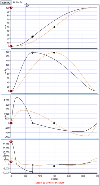
Symmetrical Motion λ = 0.5 Motion-Law : Mod-Sine Motion Law (Plot is Purple) Crossover @ 0.5 = 180º machine angle Note: The 'standard' symmetric mod-sine is one segment. However, we can use or imagine two segments, to help us understand the Asymmetric Segment 1: Segment-Width = 180º Machine angle : 0 - 180º Displacement : 0 - 0.5 units Segment-Range: 0 - 0.5 ( See : Segment Range in Segment-Editor ) Segment 2: Segment-Width = 180º Machine Angle : 180 - 360º Displacement : = 0.5 - 1.0 units Segment-Range: 0.5 - 1 Asymmetrical Motion λ = 0.25 Motion: Mod-Sine Motion-Law (Plot is White and Orange) Crossover of Asymmetric Motion: 0.25 = 90º machine angle. Asymmetrical motions are modeled with two segments- always. Segment 1: Segment-Width = 90º Machine Angle : 0 - 90º (0.25 of total duration = ) Displacement: 0 - 0.25 units (0.25 of total displacement = ) Segment-Range: 0 - 0.5 Segment 2: Segment-Width = 270º Machine Angles: 90 - 360º ( of total duration) Displacement : 0.25 - 1.0 units ( of total displacement) Segment-Range: 0.5 - 1 Coefficients (Characteristics Values: Position
Velocity
Acceleration Coefficient (Characteristic Value):
Deceleration Coefficient (Characteristic Value):
|