Pin in a Curved-Slot
Video:

Change Stroke Length of Slider with Fixed End-Point.
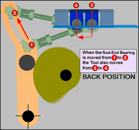 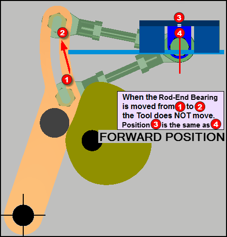 |
A Pin-in-a-Curved-Slot is frequently used in a mechanism to 'change-over' between product sizes. Why is the slot 'curved'? Because, at one end of its stroke, the tool does not move when you move the pin along the slot. At the “Back Position”, the image to the left, we make an adjustment by moving the Pin along the curved slot from As you move the Pin along the curved slot from At the “Forward Position”, the image to the right, you can see that the same adjustment does not change the position of the tool. Therefore, when you make an adjustment from How does this work? What is the radius of the Curved Slot? Where is the Curved Slot in the Orange Part? Select a Pivot-Point for the connecting-link in the Tool. Move the slider to the Design Position. This is where you do not want the Tool to move. Move the lever with the Curved-Slot to the 'Design Position' , and draw an Arc in it, with its center at the Pivot-Point in the tool Make the connecting link equal to the radius of the arc. If you need to know how to model this configuration in MechDesigner, it is really quite easy. Please email. |