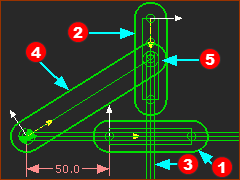
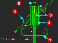
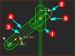
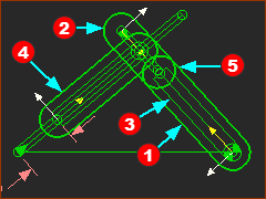
Step 2.8: Model a Pin in a Straight Slot

<< Click to Display Table of Contents >>

Navigation:  Getting Started Tutorials - MechDesigner > Tutorial 2A: Four-bar Kinematic-Chains >

Step 2.8: Model a Pin in a Straight Slot

Pin-in-a-Slot Type Mechanisms

A Pin-in-a-Slot can have many different mechanical design arrangements.

For example:

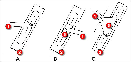
(Click to collapse) 3 x 'Pin in a Slot' designs

Click to expand: 3 x designs of 'Pin-in-a-Slot'

Design A

Red-14-1b - a part with a pin/roller at its end

Red-14-2 - a part with a linear slot

The pin/roller slides in the slot.

Design B:

Red-14-1b - a part with a Pin-Joint at its end

Red-14-2 - a part with a slot

Red-14-3 - a part that is a block (or a piston) that slides along the slot in Red-14-2 with a Slide-Joint AND a Pin-Joint to join it to the part Red-14-1b.

Design C:

Red-14-1b - a part with a Pin-Joint at its end

Red-14-2 - a part with a slot

Red-14-3 - a part that is a block (or a piston) that slides along the slot in Red-14-2 with a Slide-Joint AND a Pin-Joint to join it to the partRed-14-1b.

The Pin-Joint is offset from the axis of the Slide-Joint.


However, Designs A, B, and C must use the same kinematic-construction

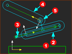
Kinematic Construction of Design C

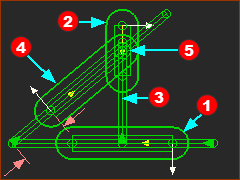
Pin-in-a-Slot - Design C

Pin-in-a-Slot - Design C


Note: In the image, the Parts are not kinematically-defined. The model needs one more joint to complete the dyad, which can be a Slide-Joint or a Pin-Joint.

These 5 Steps are the instructions of how to build the construction in the image.

STEP 1: Draw a Line* in a Part - in this case, it is a Line in the Base-Part

a)Edit a Part that is kinematically-defined**. E.g. the Base-PartRed-14-1b.

b)Add a Line*, and add dimensions and constraints to the Line*.

c)Close the Part-Editor

* Line or CAD-Line.

The Line is the axis for the cylinder (or, slot, groove, guide shaft, slide-rail, ...).

STEP 2: Add a Part

a)Press the INS(ert) key on your keyboard

b)Drag in the graphic-area, to add the PartRed-14-2.

STEP 3: Add a Slide-Joint

a)Join PartRed-14-2 to the Line in PartRed-14-1b with a Slide-JointRed-14-3

The PartRed-14-2 is now the piston (or linear-bearing, slide-block, ...)


Note:

If the Pin-JointRed-14-5 is not at the start-Point or end-Point of PartRed-14-2, we must add geometry to PartRed-14-2 to control the location of the Pin-JointRed-14-5 in PartRed-14-2. E.g: Design C , above.


STEP 4: Add a Part

a)Press the INS(ert) key on your keyboard

b)Drag in the graphic-area, to add the PartRed-14-4.


Note:

If the Pin-JointRed-14-5 is not at the start-Point or end-Point of PartRed-14-4, we must add geometry to PartRed-14-4 to control the location of the Pin-JointRed-14-5 in PartRed-14-4.


STEP 5: Add a Pin-Joint

a)Start the Add Pin-Joint command

b)Click the start-Point (or end-Point) of PartRed-14-4

c)Click the Point (see Note above) in PartRed-14-2 to add Pin-JointRed-14-5

Complete the Kinematic-Chain to add a Four-Bar

The four-bar kinematic-chain is not yet complete. The kinematic-chain:

does not have a Motion-Part - a Rocker or a Slider.

is not kinematically-defined - there are two Parts and 2 Joints (the Slide-Joint and Pin-Joint).

In the next section, you will complete the kinematic-chain. There are many possibilities.

You can add:

1.A Motion-Part - a Rocker or a Slider. It will move relative to the Base-Part

2.Join the Motion-Part to PartRed-14-4 with a Pin-Joint or a Slide-Joint.


Video:

Video: 'Pin in a Slot'. E.g Geneva Replacement.

Eight Possible Pin-in-a-Slot Kinematic-Chains

In the dyads we describe below, the letters R-P represent two joints.

The R is a Pin-Joint - R for a Revolute-Joint, which is the kinematic-term for Pin-Joint.

The P is a Slide-Joint - P for a Prismatic-Joint, which is the kinematic term for Slide-Joint.

When you add a third joint, which may be a Slide-Joint(P) or a Pin-Joint(R), the dyad is complete.

You can also join the dyad to a Rocker or a Slider. Thus, it is possible to build eight different kinematic-chains.The dyad is an R-P-R dyad. The dyad is an R-P-P dyad.The dyad is an R-R-P dyad.

Configurations:

1  & 2: RP+R + Rocker OR  RP+R + Slider.

3 & 4: RP+P + Rocker OR  RP+P + Slider.

5 & 6: R+RP + Rocker OR  R+RP + Slider.

7 & 8: P+RP + Rocker OR  P+RP + Slider.

It is also possible that the dyad in each configuration has four closures. See Change Dyad Closure.

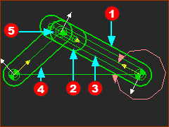
Configuration 1

Configuration 1

Configuration 1 (See Step 2.7): Rocker + R-P-R dyad

Join PartRed-14-1b to the Base-Part with a Pin-Joint

Add PartRed-14-2 .Join PartRed-14-2 to PartRed-14-1b with a Slide-JointRed-14-3. The Joint uses the CAD-Line in the two Parts.

Add PartRed-14-4. Join PartRed-14-2 to PartRed-14-4 with a Pin-JointRed-14-5

Join PartRed-14-4 to the Base-Part with a Pin-Joint. Add a Motion-Dimension FB to control PartRed-14-4 it is now a Rocker.

Note: there are many options for this dyad

Configuration 2

Configuration 2

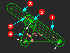
Configuration 2: Rocker + R-R-P dyad

Join the start-Point of PartRed-14-1b to the Base-Part with a Pin-Joint.

Add a Motion-Dimension FB to control the position and motion of PartRed-14-1b.

Add PartRed-14-2. Join PartRed-14-2 to PartRed-14-1b with a Slide-JointRed-14-3.

Add PartRed-14-4. Join PartRed-14-4 to the Base-Part with a Pin-JointRed-14-5.

Join the end-Point of PartRed-14-4 to the start-Point of PartRed-14-2 with a Pin-Joint.

Configuration 3

Configuration 3

Configuration 3 (See Step 2.6): Rocker + R-P-P dyad

Join CAD-Line of PartRed-14-1b to a Line in the Base-Part with a Slide-Joint.

Add a vertical Line to PartRed-14-1b.

Add PartRed-14-2. Join the CAD-Line in PartRed-14-2 to the vertical Line in PartRed-14-1b with a Slide-JointRed-14-3.

Add PartRed-14-4. Join the start-Point of PartRed-14-4 to the start-Point of a Line in the Base-Part with a Pin-Joint, Add a Motion-Dimension FB - it is now a Rocker.

Join a Point in PartRed-14-2 to the end-Point of PartRed-14-4 with a Pin-JointRed-14-5

Configuration 4

Configuration 4

Configuration 4: Slider + R-R-P dyad (or P-R-R)

Join PartRed-14-1b to the Base-Part with a Slide-Joint

Add a Motion-Dimension FB to control PartRed-14-1b - it is now a Slider

Add a vertical Line to PartRed-14-1b.

Add PartRed-14-2. Join the CAD-Line in PartRed-14-2 to the vertical Line in PartRed-14-1b with a Slide-JointRed-14-3.

Add PartRed-14-4. Join the start-Point of PartRed-14-4 to a Point in the Base-Part.

Joint the end-Point of PartRed-14-4 to a Point in PartRed-14-2 with a Pin-JointRed-14-5

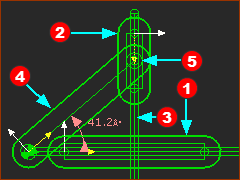
Configuration 5

Configuration 5

Configuration 5 - Slider + P-R-P dyad

Join PartRed-14-1b to the Base-Part with a Slide-Joint . Add a Motion-Dimension FB to control PartRed-14-1b - it is now a Slider

Add a vertical Line to PartRed-14-1b.

Add PartRed-14-2. Join the CAD-Line in PartRed-14-2 to the vertical Line in PartRed-14-1b with a Slide-JointRed-14-3.

Add a Line to the Base-Part at about 40º from horizontal.

Add PartRed-14-4.  Joint the CAD-Line of PartRed-14-4 to the new Line in the Base-Part with a Slide-Joint.

Joint a Point in PartRed-14-4 to a Point in PartRed-14-2 with a Pin-JointRed-14-5

Configuration 6

Configuration 6

Configuration 6 - Rocker + P-R-P dyad

Add a vertical Line to the Base-Part, and short horizontal Line)

Add PartRed-14-1b. Join PartRed-14-1b to the vertical Line in the Base-Part with a Slide-JointRed-14-3.

Add PartRed-14-4. Join the start-Point of PartRed-14-4 to the start-Point of the short Line in the Base-Part. Add a Motion-Dimension FB to control PartRed-14-4 - it is now a Rocker.

Add PartRed-14-2. Join the CAD-Line in PartRed-14-2 to the CAD-Line of PartRed-14-4 with a Slide-JointRed-14-3.

Join a Point in PartRed-14-4 to a Point in PartRed-14-2 with a Pin-JointRed-14-5

Configuration 7

Configuration 7

Configuration 7 - Slider + R-P-R dyad

Add a horizontal Line, and a Line at ~40º to horizontal to the Base-Part.

Add PartRed-14-4. Join CAD-Line in PartRed-14-4 to the Line at ~40º the short Line in the Base-Part. Add a Motion-Dimension FB to control PartRed-14-4 - it is now a Slider.

Add PartRed-14-1b. Join PartRed-14-1b to the end-Point of the horizontal Line with a Pin-Joint.

Add PartRed-14-2. Join the CAD-Line in PartRed-14-2 to the CAD-Line of Part Red-14-1b with a Slide-JointRed-14-3.

Join the end-Point in PartRed-14-4 to a Point in PartRed-14-2 with a Pin-JointRed-14-5

Configuration 8

Configuration 8

Configuration 8 -  Slider + R-P-P dyad

Add a horizontal Line, and a Line at ~40º to horizontal to the Base-Part.

Add PartRed-14-4. Join CAD-Line in PartRed-14-4 to the Line at ~40º the short Line in the Base-Part. Add a Motion-Dimension FB to control PartRed-14-4 - it is now a Slider.

Add PartRed-14-1b. Join PartRed-14-1b to the horizontal Line with a Slide-Joint.

Add a vertical Line to PartRed-14-1b

Add PartRed-14-2. Join the CAD-Line in PartRed-14-2 to the vertical Line in Part Red-14-1b with a Slide-JointRed-14-3.

Join the end-Point in PartRed-14-4 to a Point in PartRed-14-2 with a Pin-JointRed-14-5