About Element References
There are two types of Reference elements.
When you add an element:
•you may add other elements, also - for example: when you add a Line, you also add a start-Point and END-Point* .
•you may need to select other elements when you add a more complex element - for example: when you add a 2D-Cam, you need to select a Part - given the name Cam-Part - to carry the 2D-Cam.
* Points : start-Point and end-Point are the Reference elements of a Line.
To delete an element ...
To delete a Reference-element you may need to delete those elements that exist with the Reference-element.
If you will also delete other elements, the Delete Dependents warns you that you will delete the Reference-Elements in the list - if you click OK.
Show the Reference Elements dialog
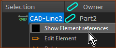
To open the Reference Elements dialog
1.Click an element in the graphics-area or the Assembly-Tree so that it is in Selection-Window
2.Right-click the element
3.Click “Show Element references” in the shortcut-menu.
Example 1: Reference-Elements of a CAD-Line:
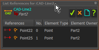
The reference elements of a Line are simple - a Start-Point and End-Point - with the name Point. Elements with the same name, have an element number. For a Line, the number that is lower than the other is the start-Point.
Therefore:
The Point22 is the start-Point of the CAD-Line
The Point25 is the end-Point of the CAD-Line
Example 2: Reference-Elements of a 2D-Cam
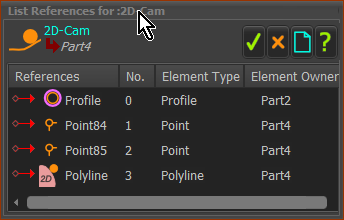
Its reference elements are:
•those elements that are in the model before you add the 2D-Cam - a Profile and a Part
•other elements you add to the 2D-Cam. E.g. Polyline, and a Profile to the Polyline.