B: ORBITING GEAR center
Epicycloid and Hypocycloid Curves to design a Lobe Pump.
You can design Lobe Pump rotors by combining Epicycloid and Hypocycloid Curves. Control the number of Lobes with the ratio of gear teeth in the Gear-Pair. Two and three lobes are common. Lobe Pumps are sometimes called Roots Blowers - after the inventor - Roots - and Blower because they were originally designed to pump air. They are often used to pump liquids with soft solids....for example fruit. MechDesigner:
SolidWorks:
|
|||
We will first add the Gears to see the complete Path. Then reduce their motion-range and their start-position. Add Point-Data FBs to measure the XY Coordinates of the External and Internal We construct one of the Rotors of the Lube-Pump and re-import to |
|||
|
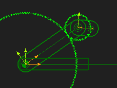
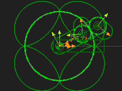
STEP 1: Add a Gear-Pair #1 - Orbiting External gear.
|
||
|
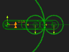
STEP 2: Add Gear-Pair #2 with an Orbiting Internal gear.
|
||
|
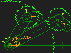
STEP 3: Edit the Motion-Dimensions for the 2 x Cranks.
|
||
|
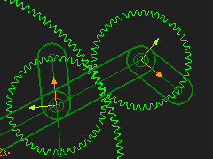
STEP 4: Edit the Geared-Rockers.
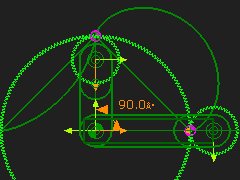
Edit the Geared-Rocker of Gear-Pair # 1 (External Mesh). Edit the Length of the CAD-Line to equal 22.5mm - its end-Point is on the Pitch-Circle of the Gear. Edit the Part that is the Geared-Rocker for the Gear-Pair # 2 (Internal Mesh). Add a Line . Dimension its start-Point = 0,0, and end-Point = -22.5, 0. The end-Point is 180º out-of-phase with the CAD-Line in the Geared Rocker. |
||
|
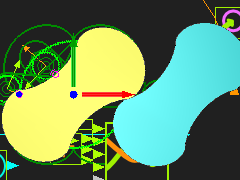
STEP 5: Add a Trace-Point to the two Geared-Rockers. The Trace-Point is the basic shape of a Two-Lobe Roots Blower. The actual shape of each rotor changes from that of the Epicycloid to the Hypocycloid path. How do we make the shape? It is easier to export the X,Y Coordinates of each section of the Lobe to SolidWorks, and use its sketch tools to construct the shape. |
||
|
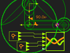
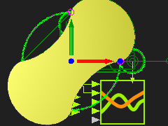
STEP 5: Add a Gearing FBs We will rotate each Crank (Driving-Gear) by 0.25 of the total rotation. Add a Gearing FB. Edit the Gearing-Ratio = 0.25 Connect it to the input of the two Motion-Dimension FB. Edit the Motion-Dimension FB for the Internal Gear-Pair. Edit its Base-Value = 90. The image is of the Trace-Points with the new settings. |
||
|
STEP 5: Measure the motion of the 2×Trace-Path Add 2 × Point-Data FBs Edit each Point-Data FB, select the Points you selected for the Trace-Point Add 2 × Graph FBs Connect the X-axis and Y-axis output-connectors from each Point-Data FB to Y-axis input-connecters of each Graph FB Note: the image has one Graph FB with 4 inputs. |
||
|
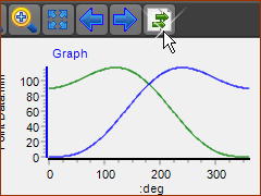
STEP 5: Export the XY motions of each Point to Excel Edit Machine Settings dialog > No. of Steps = 360 Click the icon at the RIGHT-SIDE of the Graph toolbar. A list of the graph data, at each Machine Step (see Machine Settings dialog), is to the RIGHT-SIDE of the graphs (below the X and Y-axis Data-Channel selection). |
||
 Before |
STEP 5: Paste the Data into Excel You may need to use, in Excel : Data menu > Data Tools group > Text to Columns
STEP 10: Re-arrange the Data A Curve feature needs columns of XYZ in a TXT or SLDCRV file. C column (which is the Z-data) is set to all Zeros (0). (This assumes you want the to put the Rotor on the Front-Plane in SolidWorks Save the File as a TXT file. Note: I use two(2) Graphs to give two(2) TXT files. |
||
 Ready to Save as a TXT file |
|||
|
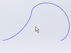
STEP 11: In SOLIDWORKS Start a new Part. For the Do Insert menu > Curve > Curve through XYZ Points... |
||
|
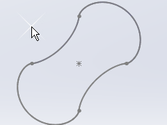
STEP 12: In SOLIDWORKS
|
||
|
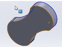
STEP 13: In SOLIDWORKS
|
||
|
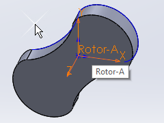
STEP 14: In SolidWorks
|
||
|
STEP 15: In MechDesigner
|
||
|
STEP 11: In MechDesigner
|
||
This is the basis for the Lobe Pump. You can add the casing etc. Usually Lobe Pumps have gears external to the casing, to drive the Lobe shafts. |
|||
When you Cycle the model, you can see there is rolling/sliding contact between the Lobes at all points in the machine cycle. In reality there should be a small clearance. A small clearance reduces the volume of fluid that can flow back through the center of the lobes. Leaks reduce the Volumetric Efficiency of the Pump. |
|||