Difference between a Motion-Part and a Motion-Point
A Motion-Part and a Motion-Point are similar elements.
Motion-Path FB & Motion-Point
 Motion-Path FB and Motion-Point |
Function-Block menu > Motion-Path FB:
After you add a Motion-Path FB, the Motion-Point is at the start-Point of the sketch-element that you select on the sketch-path. The sketch-path constrains the path of the Motion-Point. Motion-values at the input-connector to the Motion-Path FB control the motion of the Motion-Point along the sketch-path. |
|
 Motion-Path> Point-List & Data Display |
To see the dimension
** You can use the Motion-Path dialog to add more Motion-Points, but we show the Displacement or Phase of the first Motion-Point. |
Motion-Dimension FB & Motion-Part
 Motion-Dimension Rocker and Slider |
Function-Blocks menu > Add Motion-Dimension FB
A Motion-Dimension FB controls the angular position or linear position of the Motion-Part relative to a different Part. * The sketch-elements are Lines when you select a Pin-Joint - to give a Rocker. * The sketch-elements are Points when you select a Slide-Joint - to give a Slider. |
Why use a Blend-Curve?
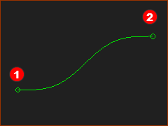 |
A Blend-Curve is a sketch-element. Use the Blend-Curve dialog to control (at its start-Point •Angle •Curvature •Rate-of-Change of Curvature •Velocity-Scaling - a normalization parameter that controls the overall length and shape of the Blend-Curve. The advantages of a Blend-Curve over Lines and Arcs, are its smoothness and how it blends with other sketch-elements at its start-point and end-Point. |
|
Questions:
|
||