Motion-Path: Ram-R and Ram-P
We can use the Motion-Path FB to build two new pseudo-dyads:
•Ram-R
•Ram-P
An application of the Ram-R dyad is to control the motion of a linear actuator that drives a scissor lift.
Kinematics of a Ram-R
|
|
Ram-R
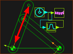
The Ram-R is a similar to an R-R-R dyad. In the Ram-R dyad, one of the two Parts can change its length.
The Ram-R uses the Motion-Path FB to add a Motion-Point to a sketch-element ( e.g. the CAD-Line along the X-axis of a Part ).
We join the other Part to the Motion-Point with a Pin-Joint.
We add a motion to the input of the Motion-Path FB to control the motion of the Motion-Point.
The Red Arrow is the path of the Motion-Point along the CAD-Line of one of the Parts.
|
|
How to add a Ram-R
|
|
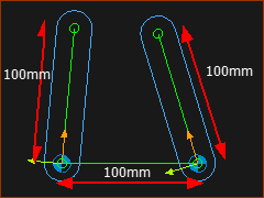
STEP 1: Add two Parts and join with Pin-Joints to a Line in the Base-Part.
1.Edit the Base-Part |
2.Close the Part-Editor
3.Add two Parts
4.Edit the length of the Parts =100mm
5.Add Pin-Joints between the start-Points of each Part and the end-Points of Line |
|
 Motion-Path FB |
STEP 2: Add a Motion-Path FB
1.Click
2.Click the  along the center of the Part (on the left in this case) along the center of the Part (on the left in this case)
3.Click  in the Command-Manager. in the Command-Manager. |
The default position of the Motion-Point is at the start-Point of the sketch-element you select - in this case the CAD-Line. is at the start-Point of the sketch-element you select - in this case the CAD-Line.
|
 Motion-Path dialog-box |
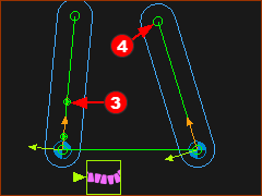
STEP 3: Edit the start Position of the Motion-Point.
There are two Parts that you have joined to the Base-Part with Pin-Joints. You will add one more Pin-Joint (See STEP 4) to give three(3) Pin-Joints in a triangular structure. To be able to add the last Pin-Joint, we must move the Motion-Point away from the start-Point.
1.Edit the Motion-Path FB
In the Point Parameters separator
2.Edit Linear Offset = 40 mm = 40 mm
3.Close the dialog |
The Motion-Point is now 40 mm from the start-Point of the CAD-Line. is now 40 mm from the start-Point of the CAD-Line.
|
|
|
STEP 4: Add Pin-Joint
1.Click
2.Click the end-Point of the Cad-Line and then the Motion-Point that is at 40 along the CAD-Line of the Cad-Line and then the Motion-Point that is at 40 along the CAD-Line |
The Pin-Joint joins the two Parts. The Ram-R dyad is now defined.
The Parts are kinematically-defined.
You may need to change the closure of the Ram-R dyad.
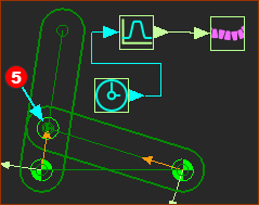
STEP 5: Change Dyad Closure
1.
2.Click the Part-Outline of one of the two Parts.
3.Click  in the Command-Manager in the Command-Manager |
STEP 6: Add a Linear Motion FB and a Motion FB
STEP 7: Edit the Motion FB and Data-Type
When you connect a Motion FB to a Motion-Path FB, you MUST edit the Output Data-Type to Linear or Rotary (the Data-Type should NOT be Motion).
1.Edit the Motion FB to open the Motion FB dialog
In the Motion FB dialog:
2.Enable Linear as the Output Data-Type
Close the dialog.
|
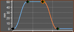
STEP 8: Edit the Motion in MotionDesigner
The maximum displacement is 50.
|
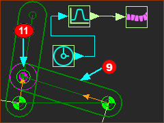
STEP 9: Connect the Linear-Motion FB to the Motion-FB to the Motion-Path FB |
|
|
Add a 2D-Cam
|
|
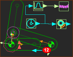
STEP 1: Add the Follower-Roller
1.Edit Part  to constrain the center of the circle to the end-Point of the CAD-Line. Exit Part-Editor. to constrain the center of the circle to the end-Point of the CAD-Line. Exit Part-Editor.
2.Do
3.Click the circle
4.Click in the Command-Manager. |
|
|
|
STEP 2: Add the Cam-Part
1.Add a Part and join it with a Pin-Joint* at the left of the Line in the Base-Part. and join it with a Pin-Joint* at the left of the Line in the Base-Part.
2.Add Motion-Dimension FB - so that Part is a Motion-Part (Rocker).
3.Connect a Linear-Motion FB to the input of the Motion-Dimension FB.
4.Edit the Motion-Dimension FB > Base-value = 0.
Part is the horizontal Cam-Part.
|
* The Select-Elements dialog opens. CTRL + CLICK the start-Point of the Part and the start-Point of the Line in the Base-Part.
|
|
|
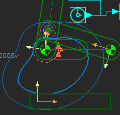
STEP 3: Add the 2D-Cam
1.Do
2.Click the new Part as the Cam-Part.
3.Click the Profile as the Follower-Profile |
The 2D-Cam is now in the graphics-area.
|
|
|
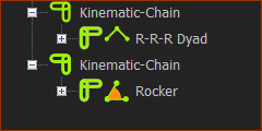
Kinematics-Tree
We call this kinematic-chain the Ram-R dyad
Kinematic-Chain #1 : The R-R-R is the Ram-R dyad - normally, this would be a structure. But a motion controls the length of one of the Parts in the dyad.
Kinematic-Chain #2 :The Rocker represents the Cam-Shaft.
|