MOTION-LAWS CHARACTERISTIC VALUES
Use Motion-Law Characteristic Values DE: Kennwert to compare motions that you design with Traditional Motion-Laws.
Motion-Law Coefficients
Label |
Name |
Nominal Relevance |
|---|---|---|
|
Velocity Coefficient |
A measure of the maximum Pressure Angle between the |
|
Acceleration Coefficient |
A measure of the maximum Inertia Force. |
|
Jerk Coefficient |
A measure of the risk of vibration excitation of the follower-system. |
The Motion-Law Coefficients are equal to the maximum motion-values for the motion-derivatives when the motion has a:
•period and
•displacement (linear or angular).
Maximum Velocity, Acceleration, and Jerk values
For any rise or return segment, you can calculate the actual maximum motion-values from the its Motion-Law Coefficients . You need to know the segment's motion-law, maximum displacement, , and motion period, .
Actual Maximum Velocity = |
|
Note: If you reduce the motion-period, , by about 10% the : •maximum velocity increases by ~10%, •maximum acceleration increases by ~20% •maximum jerk increases by ~40% |
Actual Maximum Acceleration = |
|
|
Actual Maximum Jerk = |
|
Drive Torque Coefficients or Factors
Usually, it is desired that the cam-shaft rotates at constant angular velocity. However, a typical force-closed cam-follower system imposes three torque components onto the cam-shaft.
We use Torque Factors to get a sense of the magnitude of each component.
Torque Factors |
Torque Factor |
Nominal Relevance |
|
|---|---|---|---|
Constant Load |
= |
The component of drive torque required to overcome the constant load from the follower-system, e.g. from the gravitational weight of the follower, pre-load on a spring, and friction. Usually the least significant Torque Factor. Also termed |
|
Inertia Load |
|
The component of drive torque required to accelerate the mass or mass moment of inertia of the follower-system. Usually the most dominant. Also termed |
|
Spring Load |
|
The component of drive torque required to overcome the linear increase in force as a spring is compressed in the follower-system to keep the Follower-Roller against the Cam-Profile. |
|
where |
|
= normalized displacement (0 1) |
|
|
|
= non-dimensional velocity |
|
|
|
= non-dimensional acceleration |
|
Note on Input Torque Coefficient
The maximum torque required to drive the cam Follower is important. However, the rate-of-change of torque at the crossover, as it changes from positive to negative torque is also important, if not more important. A positive input torque on the cam-shaft winds-up (twists) the cam-shaft. A negative torque winds-down (untwists) the cam-shaft. The Torque changes from a positive to a negative value at the crossover. As backlash is traversed at crossover, the Torque at the input reduces to only the 'friction torque'. The result is the speed of the drive-motor and cam-shaft may increase rapidly. This will increase the impact shock as any backlash is traversed. If the speed of the motor does increase, the motion-law at the output is distorted and the maximum values of velocity and deceleration increase when the cam-shaft momentarily increases its speed. |
Power
Constant Power
|
Power - constant Torque and constant Angular Velocity |
|
Power - constant Force and constant Linear-Velocity |
Instantaneous Power
Of course, Torque and Angular Velocity at the Follower continuously change throughout the motion. Thus, the Power at the output shaft also changes continuously.
The Instantaneous Power, when calculated at the output is:
|
Instantaneous Power - varying Torque and Angular Velocity |
|
Instantaneous Power - varying Force and Linear-Velocity |
Total Load Torque or Load Force are found from values of Mass Moment of Inertia, Mass, and Acceleration.
However, the:
•Acceleration continually changes throughout the motion - of course.
•Load Mass Moment of Inertia and Mass, referred to the drive-shaft, can be constant (e.g. Dial-Plate) or can continually change (e.g. Toggle mechanism).
In the general case, the Load Mass Moment of Inertia and Mass that are reflected to the Follower vary throughout the motion.
The instantaneous Load Torque and Load Force are:
|
Instantaneous Load Torque with changing Load Mass Moment of Inertia and/or Angular Acceleration. |
|
Instantaneous Load Force with changing Load Mass and/or Linear Acceleration |
Also, the instantaneous Load Power is:
|
Load Power with changing Load Mass Moment of Inertia, Angular Acceleration, and Angular Velocity. |
|
Load Power with changing Load Mass, Linear Acceleration, and Linear Velocity. |
When reflected Load Mass Moment of Inertia is not a function of the motion, the Power-Coefficient is less complex.
The instantaneous Load Power, with constant reflected Load Mass Moment of Inertia or Load Mass is:
|
Load Power with constant Load Mass Moment of Inertia, Angular Acceleration, and Angular Velocity. |
|
Load Power with constant Load Mass, Linear Acceleration, and Linear Velocity. |
Power Coefficient
|
MOTION COEFFICIENTS OF THE TRADITIONAL MOTION-LAWS
Motion-Law Name |
Velocity Coefficient
|
Acceleration Coefficient
|
Input Torque Coefficient
|
Power Coefficient
|
|---|---|---|---|---|
Constant Acceleration Parabolic |
2 |
4 |
2 |
8 |
Simple Harmonic |
1.570796 |
4.934803 |
0.785 |
3.8758 |
Cycloidal |
2 |
6.283185 |
1.298 |
8.1621 |
Modified Trapezoid |
2 |
4.888124 |
1.655 |
8.0894 |
Polynomial 3-4-5 |
1.875 |
5.773503 |
1.159 |
6.6925 |
Polynomial 4-5-6-7 |
2.1875 |
7.5132 |
1.431 |
10.750 |
Modified Sine |
1.759603 |
5.527957 |
0.987 |
5.4575 |
SINE-CONSTANT-COSINE ACCELERATION (SCCA) with CONSTANT VELOCITY
Edit the Segment Parameters (with the Segment Editor) of the Sine-Constant-Cosine Acceleration (SCCA) Motion-Law to give many of the popular motion laws for industrial cams.
Motion-Law Name |
Coefficients |
SCCA Parameters (Factors) |
|||
|---|---|---|---|---|---|
Velocity Coefficient
|
Acceleration Coefficient
|
a |
b |
c |
|
Modified-Sine CV 0% |
1.760 |
5.528 |
0.25 |
0 |
0.75 |
Modified-Sine |
1.528 |
5.999 |
0.2 |
0 |
0.6 |
Modified-Sine |
1.404 |
6.616 |
0.1667 |
0 |
0.5 |
Modified-Sine |
1.275 |
8.0127 |
0.125 |
0 |
0.375 |
Modified-Sine |
1.168 |
11.009 |
0.0833 |
0 |
0.25 |
Cycloidal |
1.333 |
8.378 |
0.25 |
0 |
0.25 |
Trapezoidal Velocity CV 33% |
1.5 |
4.5 |
0 |
0.6667 |
0 |
3-HARMONIC MOTION-LAWS
Edit the Segment Parameters (in the Segment Editor) of the Triple Harmonic Motion-Law to give alternatives to some of the popular motion-laws.
Motion-Law Name
|
Coefficients |
Harmonic |
|||
|---|---|---|---|---|---|
Velocity Coefficient
|
Acceleration Coefficient
|
1st |
2nd |
3rd |
|
3-Harmonic |
2.0 |
5.16 |
5.96 |
0 |
0.9696 |
3-Harmonic |
1.72 |
6.07 |
5.1968 |
1.7690 |
0.6057 |
3-Harmonic |
2.0 |
9.42 |
|
0 |
|
MOTION-LAWS COMPARED - for Initial Selection
We can compare and “score” the common Traditional Motion-Laws. The score can help you select a law when you start a motion and machine design. The scores range from 1 (relatively bad) to 5 (excellent). They apply to Dwell-Rise Dwell type motions.
If we look at the table, it can be seen that, of the laws listed, that the Modified Sine(MS) is the best for general purposes. Its particular merit is that it is very tolerant of a bad input drive and transmission (elasticity, backlash, wear, low inertia). It is frequently the first choice of cam designers and is almost always used by commercial manufacturers of cam-operated indexing mechanisms.
Additionally, you can look at the Motion-Law Coefficients of the common cam motion-laws. These indicate the relative values of their Velocity Coefficient and Acceleration Coefficient.
Cam Law |
Peak Acceleration |
Output Vibration |
Peak Velocity |
Impact |
Input Torque |
Input Vibration |
Residual Vibration |
|---|---|---|---|---|---|---|---|
Parabolic |
5 |
1 |
2 |
1 |
1 |
1 |
1 |
Simple Harmonic |
3 |
1 |
4 |
4 |
5 |
2 |
1 |
Modified Trapezoid |
3 |
3 |
2 |
2 |
2 |
3 |
3 |
Modified Sinusoid |
2 |
4 |
3 |
4 |
4 |
4 |
4 |
Cycloidal |
1 |
5 |
2 |
3 |
3 |
4 |
5 |
Explanatory Notes
Peak Acceleration This merit rating applies to the nominal maximum output acceleration during the motion period, calculated by the motion-law equation. |
Output Vibration Output vibration is superimposed on the nominal output acceleration, thereby increasing the nominal peak value. The vibration severity depends on the elasticity and operating speed of the mechanism. The merit rating applies to mechanisms of average rigidity running at fairly high speed. |
Peak Velocity Peak Velocity is the nominal maximum output velocity during the motion period, calculated by the motion-law equation. Its value is also increased by superimposed vibration. |
Impact / Backlash Impact forces occur at the locations of backlash in the mechanism when the changeover from acceleration to deceleration occurs. The severity of the impact depends on how gradually the changeover takes place. That is, how low the jerk is at point of impact. Strictly speaking, it is the changeover from positive to negative force or torque that matters, but in most high speed systems, that almost coincides with the acceleration changeover. |
Input Torque The nominal input torque of a mechanism varies throughout the motion period and is a function of the output load profile, and the velocity pattern. The peak acceleration and the peak velocity do not coincide and neither coincides with the peak input torque. Motion-Laws with good, that is low, acceleration do not necessarily have good input torque. |
Input Vibration The elasticity and backlash of the input transmission can cause serious over-run and input-vibration. This is when the sudden reversal of the input torque when the load crosses over from acceleration to deceleration - or load - causes the cam to jump forwards before it can transmit a decelerating force to the output. The more gradual that the nominal input torque changes sign, the less severe is the overrun and its consequences. |
Residual Vibration Residual Vibration takes place in the dwell period immediately following the motion period in high speed or elastic systems. Its amplitude depends on the vibration generated during the motion period, and the degree of damping present in the output transmission. It is very difficult to add sufficient damping to high speed mechanisms to eliminate residual vibration, so the choice of a motion-law is vital in some cases. |
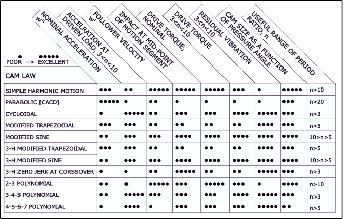
Motion Laws Compared - another table.
This table includes 'Period Ratio' as a parameter with which you can select a Motion-Law. It is from an ESDU* item.
* Engineering Science Data Unit, published in the UK.