Segment Blending and Motion Continuity
see also: Impact, Acceleration Shock, How to Blend Two Segments
 Motion-Law Discontinuity |
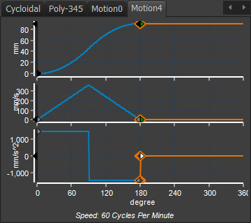
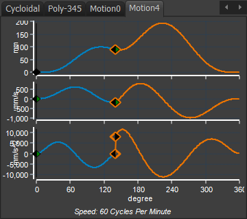
Motion Discontinuity Definition. A motion discontinuity is one in which the Y-axis of a motion-derivative has two values at one instant on its X–axis. The name of the motion-discontinuity refers to the lowest motion-derivative at which the motion-discontinuity occurs. In the image above, the motion-law uses the Constant Acceleration & Deceleration Motion-Law. It has three(3) acceleration discontinuities. The motion discontinuity of the acceleration at the mid-point is the most aggressive, as it changes from the maximum acceleration to the maximum deceleration. In the image below, the motion also has an Acceleration-Discontinuity. All motion-discontinuities can be eliminated, including Jerk, if you use the Flexible-Polynomial motion-law. |
 Segment Discontinuity |
Segment Blending
Segment Blending considers the motion-values at the Blend-Points.
It is recommended that you design your motions with at least Position, Velocity, and Acceleration continuity.
Jerk continuity may also be appropriate, but not in all circumstances.
IMPORTANT - In MotionDesigner, It is possible to design a motion with motion-discontinuities at any motion-derivative, even Position.
Clearly, the mechanical system does not move from one position to the next in zero time. It does not have a positional motion-discontinuity.
Position Continuity
A Step-change in Position? A Position motion-discontinuity is needed with a progressive (indexing) motion. Mechanical systems cannot respond to a Position-Discontinuity - to move from one position to a different position in zero time! It would be a magic trick! Cartoon characters can do this motion, but not mechanical systems. A Cam would need a step in it. You must use at least the Match Control button in the Segment and Blend-Point Editors to give Position-Continuity. |
Velocity Continuity
A Step-change in Velocity? Mechanical system cannot respond to a Velocity-Discontinuity. You are trying to make the system respond as if it has been hit. A Servo motor would need to change its speed instantly, with infinite acceleration. This is unattainable. A Cam would have a corner, or kink. |
Acceleration Continuity
A Step-change in Acceleration? Mechanical systems vibrate in response to an Acceleration-Discontinuity. Do this experiment to see an Acceleration-Discontinuity: 1.Clamp (or hold down) a 300mm ruler at one end, so it hangs over the edge of a table. 2.Release a coin from zero height onto the ruler, near to its end. The velocity-impact is zero because you release the coin from zero-height. The ruler experiences a step change in force (gravitational force) as you release the coin on to it. The ruler vibrates with a displacement amplitude of about two times the final resting position of the ruler with the coin on it |
Jerk Continuity
A Step-change in Jerk? Jerk-Continuity gives the least mechanical vibration in the mechanical system, at the expense of higher peak nominal accelerations. Note Zero-Jerk Rise or Return Segments when bounded with Dwell Segments If a segment has zero-jerk at its start-end end, e.g. the Polynomial 4567 motion-law, you will notice that the maximum acceleration and decelerations are very high when compared to sat the Polynomial 345. If the segment is bounded before and after with a dwell segments, you can frequently decrease the duration of the each dwell segment by 10º and increase the duration of the Poly 4567 segment by 20º. Then, the maximum acceleration is much less and there is jerk-continuity. |