Torque and Gearing Ratio
This is a simple example that illustrates that the gearing ratio between the load and the output shaft of an indexer is very important.
Your machine has a fixed payload. It is:
•A Rotary Table
•A Table Rotation of per Index
•A maximum Load Torque of .
Since an indexer with a Number-of-Stops = is not available, you must apply a gearing ratio between the table and indexer.
Let us look at two solutions that use two different pulley size ratios:
|
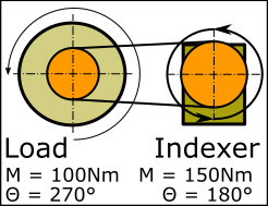
SOLUTION 1 •2 stop indexer •Index-angle = 180° per stop •A transmission ratio of 3 : 2 between the indexer output and rotary table. The Belt and Pulleys increase the output to 270° per index of the rotary table. The Torque at the indexer output : |
|
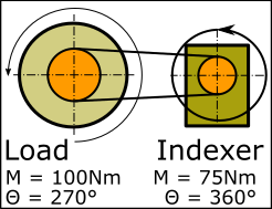
SOLUTION 2 •1 stop indexer •Index angle = 360° per stop •A transmission ratio of 3 : 4 between the indexer output and rotary table. The Belt and Pulleys reduce the output to 270° per index of the rotary table. The Torque at the indexer output :
|