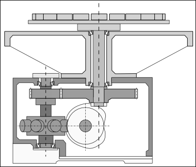
Indexing Table with Backlash.
 Mechanical Layout of the Indexing Table |
Table •20 workstations, at Ø500mm P. C. D. (Pitch Circle Diameter) •Mass of each station = 1.5kg. •Steel Table, Diameter Ø600mm, 16mm Thick. •8-Stop Globoidal cam indexer through gears with a 2.5 : 1 reduction ratio. The table is directly attached to the main shaft •It is Ø50mm x 320mm long. •The length of the main shaft that is in torsion form the underside of the table to the center of the large gear is 275mm. Gears •The gears are Ø128mm and Ø320mm x 40mm wide, made of Steel. Indexer •The indexer turret is Ø163mm x 80mm thick. It has 8 rollers Ø2" x 1.25" long, on a pitched circle of Ø195mm. •The indexer turret is mounted on a shaft Ø50mm x 208mm long. •The length of the turret shaft that is in torsion is 137mm. |
||||||||||||||||||||||||||||||||||||||||||||||||||||||||||
Motion-law is Mod-Sine, 180º index-period, and runs at 150RPM. The cycle time is 0.4s, with 0.2s motion and 0.2s dwell. The cam-shaft runs at constant angular velocity. Overall Friction Torque of 2.0N.m in the output transmission referred to the indexer turret. The maximum backlash permitted in the cam track, when manufactured is 0.04mm. The backlash in the gears can wear to 0.1mm before adjustment or replacement. Mass and Inertia of Components
The mass and inertia of each component are calculated as shown in the table above. The Combined Total Inertia in the above table takes into account the gear ratio. The inertia of the slow-speed assembly is reduced by the square of the gear ratio when referred to the indexer turret shaft. ... an illustration of the benefits of a speed reduction. Assessment of Dynamic System.To assess the dynamic response, we estimate the natural vibration frequency of the system, and from that, the Period-Ratio. The gears have a significant mass and inertia in an intermediate position in the transmission, which means that the system will not vibrate with a single, simple frequency, as required by the foregoing dynamic response theory! However, the high inertia of the table and work stations imposes a dominant frequency which gives a good approximation to the theoretical model: this is nearly always the case in practice. But, be aware. Rigidity
Turret Shaft Torsional Rigidity
Second moment of area of shaft is:
Main Shaft Bending Stiffness is:
Radius of Large Gear = 0.16m: Its equivalent Torsional Rigidity is:
Indexer High Speed Shaft Torsional Rigidity
Turret Bending Stiffness is:
Radius of Small Gear = 0.064m Its equivalent Torsional Rigidity is:
The combined rigidity, referred to the indexer turret:
(Note that the bending stiffness is so high it could have been ignored). Approximate Natural Frequency
Natural Period = (assuming a single degree of freedom). Period-RatioThe motion period is 0.2 seconds. The Period-Ratio is:
Nominal Peak Inertia TorqueThe total inertia referred to the indexer is
Peak Angular Acceleration: The output stroke of the indexer is:
Index-Period of the Indexer is:
The Coefficient of Acceleration of the Mod-Sine is:
Nominal Peak Acceleration is:
Peak Inertia Torque after Torque-FactorTorque-Factor We can use this equation to find the Torsion-Factor
The Parameters for the Mod-Sine Motion-Law are: ; ; The Period-Ratio, n. is 6.34 Using the parameters, the Torsion-Factor is
We must increase the Nominal Peak Inertia Torque by the Torsion-Factor:
Add Friction TorqueWe must add the Friction Torque for the mechanism, ignoring the backlash impact effect.
Include BacklashWe must consider the impact shock load after the transition of backlash... Total Backlash, expressed as an angle (radians), at the Indexer Turret.
Normalized backlash (backlash against angular stroke)
Deceleration The natural deceleration of the system due to the deceleration torque on the payload during 'Free-Flight' is:
Normalized Deceleration is:
This is quite low and can be taken as Zero! Normalized Impact VelocityWith a Normalized Backlash of 0.00251 and Normalized Deceleration of 0.0, then: Normalized Impact Velocity: Real Impact Velocity:
Peak Shock TorqueThe Peak Shock Torque on the Turret is:
At 40% of the Peak Inertia Torque without Backlash, this is a significant load, and should not be ignored in the design of the mechanism. A safe way of taking it into account is simply to add it to the peak vibration torque (this assumes the two peak torques occur at exactly the same point in the motion, which is quite possible): Peak Torque at Output Shaft.Add the Peak Shock Torque to the Vibration Torque
Although it could be argued that this is too pessimistic, it does illustrate that to design the mechanism on the basis of the Nominal Dynamic Torque of 78.41Nm would be under-estimated! |
|||||||||||||||||||||||||||||||||||||||||||||||||||||||||||