This topic describes how you can calculate the values for an Asymmetric Rise or Return Segment.
See the on-line Getting Started Tutorials: MotionDesigner to see how you can design an asymmetric segment in MotionDesigner.
First, it is useful to look at normalized symmetric rise segments.
6 Normalized Symmetric Rise Segments

Normalized Displacement Plots of 6 different motions laws, with zero-velocity at the start and end of each.
The image above shows 6 normalized symmetric rise segments motion-laws.
While the motion-laws are clearly different, the common characteristics of all Normalized Motion-Laws are as follows:
Period : |
|
Rise displacement : |
|
Zero velocity at the start and end of the segment : |
|
Zero acceleration at the start and end of the segment* : |
|
Maximum velocity at the mid-point of the segment : |
|
Equal acceleration and deceleration periods :
|
|
Asymmetry Factor: |
|
* Zero acceleration at the start and end of good motion-laws, while others, e.g. the Parabolic† motion-law, may have acceleration discontinuities. † Parabolic motion-law is another name for the Constant-Acceleration and Constant Deceleration motion-law. |
|
Normalized Symmetric Segment
The image below shows the normalized displacement, velocity, and acceleration plots for the symmetric Parabolic motion-law, in which the Asymmetry Factor is , that is, it is Symmetric.
You can see that the:
•Acceleration phase is from , and the deceleration phase is from . The period of the phases are equal to each other.
•The inflection point of the displacement plot, at maximum velocity, and as acceleration changes to deceleration, is on the diagonal .
The Asymmetry Factor, .
0

Symmetric Nomralized Parabolic Rise Segment
Normalized Asymmetric Segment
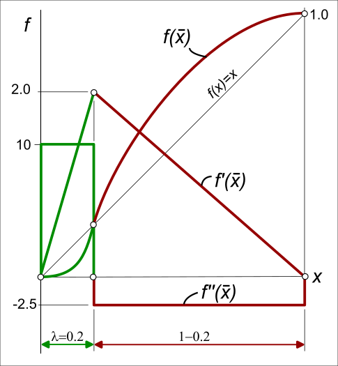
The image below shows the normalized displacement, velocity, and acceleration plots for an asymmetric Parabolic motion-law, in which the Asymmetry Factor is .
In the example:
•Acceleration phase is from , and the deceleration phase is from
•The inflection point of the displacement plot, at maximum velocity, and as acceleration changes to deceleration, is on diagonal:
•The maximum normalized acceleration values have increased from 4 (symmetric) to 10 (asymmetric).
•The maximum normalized velocity value of the asymmetric segment is equal to that of the symmetric segment
The Asymmetry Factor, .
How to calculate the motion values of an Asymmetric Motion Law
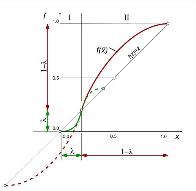
It is helpful to imagine that the asymmetric motion as two half segments, or phases.
The X-axis and Y-axis of the solid green plot are from - it is the acceleration phase of the asymmetric motion.
Hence, to calculate the values for the green part of the segment, we need to “shrink” the X-axis and Y-axis.
The X-axis and Y-axis of the solid red plot are from - it is the deceleration phase of the asymmetric motion.
Hence, to calculate the values for the red part of the segment, we need to “stretch” the X-axis and Y-axis.
The factors for the “shrink” Phase and the “stretch” Phase , are below.
Phase :
Scale the X-axis |
|
Scale the displacement, and use to calculate |
|
Scale the velocity, and use to calculate |
|
Scale the acceleration, and use to calculate |
|
Phase :
Scale the X-axis |
|
Scale the displacement, and use to calculate |
|
Scale the velocity, and use to calculate |
|
Scale the acceleration, and use to calculate |
|