Math FB
Note:
Equations
Motion-Derivatives
Units
|
What can you do with a Math FB?
You can use the Math FB to do:
|
How to add the Math FB and Open the Math FB dialog/interface.
|
||
Add a Math FB:
The Math FB is now in the graphics-area Open a Math FB dialog
The Math FB dialog is now open |
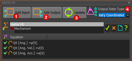
Math FB dialog
|
|||
Add Input You need one input-connector for each variable or parameter in your equation.
Add Output You need one output-connector for each variable and its motion-derivative
Output Data-Type
|
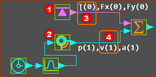
Wire Numbers and Data-Channels
The format of each parameter is an equation is: Data-Channel (Wire-Number)  Three wires connected to the input of a Math FB The image above has three(3) Wires connected to three input-connectors of a Math FB. Wire-Numbers - IMPORTANT : Wire-Numbers start at 0
Data-Channel
Example Entries in an Equation:
|
How many input and output-connectors? - and Example:
It is easier to understand with an example. We will calculate Power :
|
||
|
||
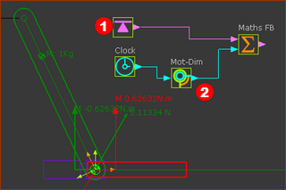
Prepare the model:
|
||
|
||
See image above - note the three Data-Channels at output-connectors of the Force-Data FB and the Motion-Dimension FB. Prepare the Math FB:
The Math FB uses SI units for all data at its input-connectors
|
||
 MathFB- |
||
SYNTAX and VALID Equations:
|
Function-Blocks : Data-Types & Data-Channels
Output-Connector from : |
Output Data Type |
Data-Channel 1 |
Data-Channel 2 |
Data-Channel 3 |
|---|---|---|---|---|
Linear Motion FB |
Rotary |
Machine Angle |
Machine Angular Velocity |
Machine Angular Acceleration |
Gearing FB |
Linear |
Position - mm |
Linear Velocity - mm/s |
Linear Acceleration - mm/s/s |
Rotary |
Angle - deg |
Angular Velocity deg/s |
Angular Acceleration deg/s/s |
|
Motion FB |
Linear |
Position - mm |
Linear Velocity - mm/s |
Linear Acceleration - mm/s/s |
Rotary |
Angle - deg |
Angular Velocity - rad/s |
Angular Acceleration - deg/s/s |
|
Motion-Dimension FB |
Linear |
Position (mm) |
Linear Velocity -mm/s |
Linear Acceleration - mm/s/s |
Rotary |
Angle -deg |
Angular Velocity -rad/s |
Angular Acceleration - rad/s/s |
|
Measurement FB |
Linear |
Position - mm |
Linear Velocity - mm/s |
Linear Acceleration - mm/s/s |
Rotary |
Angle -deg |
Angular Velocity -rad/s |
Angular Acceleration - rad/s/s |
|
Point-Data FB (3 output-connectors) |
Linear Linear Linear |
X Position mm Y Position - mm Magnitude - mm |
X Velocity - mm/s Y Velocity - mm/s Mag. Velocity- mm/s |
X Acceleration - mm/s/s Y Acceleration - mm/s/s Mag. Acceleration - mm/s/s |
Cam-Data FB (5 output-connectors) |
Rotary |
Pressure Angle - deg |
Contact Pressure Angel 1 - deg |
Contact Pressure Angle 2 - deg |
Linear |
Inner Cam Radius-of-Curvature |
Outer Cam Radius-of-Curvature |
------ |
|
Force |
Contact Force Total - N |
Contact Force, X component - N |
Contact Force, Y component |
|
Stress/Pressure |
Inner Cam Shear Stress- N/mm2 |
Outer Cam Shear Stress - N/mm2 |
------ |
|
Linear |
Sliding-Velocity (mm/s) |
------ |
------ |
|
Force-Data FB |
Force |
Joint Total Force / Torque |
X Component - N |
Y Component - N |
Force |
Cam Contact Force - N |
X Component - N |
Y Component - N |
|
Force |
Spring Force - N |
X Component - N |
Y Component - N |
|
Math FB |
See Math FB dialog |
|||