Add an Orbiting Pulley

<< Click to Display Table of Contents >>

Navigation:  Getting Started Tutorials - MechDesigner > Tutorial 17: Belts and Pulleys > Step 17.3: Option 2 - Orbiting Pulley Center >

Add an Orbiting Pulley

An Orbiting-Pulley has an Orbiting center:
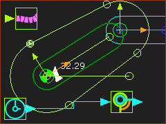
The center of one Pulley revolves, or orbits, around the center of a different Pulley.

A sketch of the Belt is in a rotating-Part that connects the centers of the two Pulleys.

Preparation

Line in the Base-Part

Line in the Base-Part

STEP 1: Add a rotating-Part - a Crank

1.Edit the Base-Part

2.Part-Editor: Geometry toolbar > Add Line. Drag from left to right-to add the Line.

3.Part-Editor: Constraints toolbar > Add Horizontal | Click the Line.  (Add dimensions also to fully constrain the Line )

4.Exit the Part-Editor

Add Motion-Dimension FB - rotating-Part

Add Motion-Dimension FB - rotating-Part

5.Kinematic-element toolbar > Add Part (INSERT key as shortcut)

6.Drag to add the Part

7.Kinematic-elements-toolbar > Add Pin-Joint | Click the start-Point of the new Part and the start-Point of the Line in the Base-Part.

8.Kinematic-FBs toolbar > Add Motion-Dimension FB | Click the Pin-Joint, the horizontal Line, and the CAD-Line in the Part.

9.Click OK-tiny-11-15 in the Command-Manager.

Sketch-Path on the Crank

Sketch-Path on the Crank

Crank and Motion-Path FB

Crank and Motion-Path FB

STEP 2: Add a sketch-path to represent the path of the belt.

1.Edit the rotating-Part

Add the sketch-path to represent the path of the Belt. As you add the sketch-elements, use the Hover + Drag technique (faster) or use Merge-Points in the Part-Editor.

2.Part-Editor: Geometry toolbar > Add Line x 2 | Drag to add the Lines approximately parallel to the X-axis of the Part - see sketch to the left

3.Part-Editor: Geometry-Editor > Add Arcs x 2 | Hover + Drag from the end-Point of a Line to the start-Point of a Line, then Drag again to approximate the radius of the arc.

4.Part-Editor: Constraints toolbar > Add Coincident | Click the center-Point of an Arc then the start-Point of the CAD-Line at the Origin of the Part.

5.Part-Editor: Constraints toolbar > Add Coincident | Click the center-Point of an Arc then the X-axis of the Part.

6.Part-Editor: Geometry toolbar > Add Dimension | Click each Arc to define the radius of each Arc.

7.Exit the Part-Editor

STEP 3: Add a Motion-Path FB to the sketch-path

1.Mechanism-Editor: Kinematic-FBs toolbar > Add Motion-Path FB

2.Mechanism-Editor:  Click the sketch-path - the belt.

3.Click OK-tiny-11-15 in the Command-Manager

GST-T17-O2-Orbiting-Pulley-006

STEP 4: Add a Linear-Motion FB

1.Mechanism-Editor: Kinematic-FBs toolbar > Add Linear-Motion FB | Click the graphic-area

STEP 5: Add a Part

Add a Part to the other end of the sketch-path. We will add a Pulley to this Part also - see below.

Add Pulley × 2

GST-T17-O2-Orbiting-Pulley-007

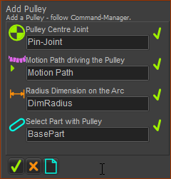
STEP 1: Start the Add Pulley command

GST-Icon-AddPulley

1.Click Machine-elements toolbar > Add Pulley

The Command-Manager has four selection-boxes.

STEP 2: Select the elements for the Pulley

1.Click the Pin-Joint at the origin of the rotating-Part.

2.Click the Motion-Path FB

The Part-Editor opens with the sketch-path that represents the Belt

3.Click the Dimension of the Arc sketch-element at the origin of the CAD-Line

The Part-Editor closes.

4.Click the Base-Part.
Select the Base-Part because the Pulley is fixed to the Base-Part.

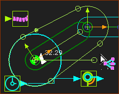
The Pulley. has a Cyan color. It is a Driving-Pulley.

See also: Application-Settings > Graphics tab > Display Colors.

STEP 3: Start the Add Pulley command AGAIN

GST-Icon-AddPulley

1.Click Machine-elements toolbar > Add Pulley

GST-T17-O2-Orbiting-Pulley-008

GST-T17-O2-Orbiting-Pulley-009

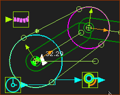
STEP 4: Select the elements for the Pulley AGAIN

1.Click the Pin-Joint at the origin of the Part at the end of the belt-path.

2.Click the Motion-Path FB - we click the same Motion-Path FB as it is the same belt-path.

The Part-Editor is open with the sketch-path the represents the Belt.

1.Click the Dimension of the Arc sketch-element at the end of the belt-path.

The Part-Editor closes:

2.Click the Part at the other end of the belt-path

The Pulley has a Magenta color. This means it is a Driven-Pulley.