Application of Orbiting Pulley center

<< Click to Display Table of Contents >>

Navigation:  Getting Started Tutorials - MechDesigner > Tutorial 17: Belts and Pulleys > Step 17.3: Option 2 - Orbiting Pulley Center >

Application of Orbiting Pulley center

This application is a simple and cheap indexer. However, the output has motion-discontinuities. Therefore, I would not use it for a high-speed machine unless the load inertia is small.

Add an Orbiting Pulley and edit the length of the Belt

GST-T17-O2-Orbiting-Pulley-B001

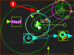
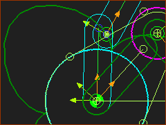
STEP 1: Do Orbiting Pulley center

STEP 2: Add a Trace-Point to the Motion-Point.

1.Do Kinematic-element toolbar > Add Trace-Point

2.Click the Motion-PointRed-14-1b

3.Run menu > Cycle)

The Motion-Point moves along the Trace-Point.

To construct a 3-Stop Indexer, the Trace-Point must trace exactly three lobes (flower-petals) around the fixed Pulley.


GST-T17-O2-Orbiting-Pulley-B001a

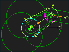
STEP 3: Add a Gearing FB to increase the number of rotations of the Crank

1.Do Kinematic-FBs toolbar > Add Gearing FB | Click the graphic-area.

2.Delete the wire between the Linear-Motion FB and the Motion-Dimension FB

3.Connect a wire between the Linear-Motion FB and the Gearing FB, and also between the Gearing FB and the Motion-Dimension FB

4.Edit the Gearing FB,

5.Enter Gearing Ratio = 4

The Trace-Point has more lobes. However, the Trace-Point does not end where it starts.

Edit these parameters in these elements:

Pulley : Number of Teeth

Motion-Path FB : Length of the Belt, Tooth-Pitch


STEP 4: Edit each Pulley

1.Double-click each Pulley to open the Pulley dialog (or see How to open a dialog)

a.Fixed Pulley dialog > Number of Teeth =120

b.Moving Pulley dialog > Number of Teeth =40

Note

The read-only parameters in the Pulley dialog

Pitch-Circle Diameter ( = (Tooth Pitch × Number-of-Teeth) / π )

Tooth Pitch (Edit Belt-Pitch in Motion-Path dialog)

Belt Length (Edit Target Path Length in Motion-Path dialog)

Pulley dialog: Number-of-Teeth

Pulley dialog: Number-of-Teeth

Motion-Path dialog No Control-Dimension 

Motion-Path dialog
No Control-Dimension 

Motion-Path FB with a Control Dimension

Motion-Path FB
with a Control Dimension

STEP 5: Edit the Motion-Path FB.

1.Double-click the Motion-Path FB (or see How to open a dialog)

2.Length Control tab >  Control Length of Belt 

Dimension : not assigned

Actual Path Length = 830.283mm - read-only

Target Path Length = 100mm - read-only

Control-Dimension Min = 0mm - read-only

Control-Dimension Max = 0mm - read-only

3.Length Control tab > Belt Tooth-Pitch  >Belt Tooth Pitch = 5 mm

STEP 6: Select a Control-Dimension

We must select a dimension with which the dialog can control the length of the Belt.

1.Click the Start Length-Control button

The Part-Editor opens to edit the Part and sketch-path of the Belt.

Select the CONTROLLING DIMENSION

Select the CONTROLLING DIMENSION

1.Click the dimension you want to use to control the length of the Belt

In this case, click the dimension that controls the distance between the two arcs and Pulleys.

< see image to the left.

The Part-Editor closes automatically.

STEP 7: Review the Motion-Path dialog

Dimension name :   DIMPtoP5 - read-only

Control-Dimension Length = 205.184mm  - read-only

Actual Path Length = 830.283mm - read-only

Target Path Length = 830.2833223mm - read-write

Control-Dimension Min = 41.0367...mm - read-write

Control-Dimension Max = 1025.919...mm - read-write

You should see that the Actual Path Length is equal to the Target Path Length.

If not, then the algorithm has not found a good solution.

We may need to narrow or widen the search space for the algorithm.

1.Edit Control-Dimension Min and/or Control-Dimension Max by small increments.

Eventually, you find the Actual Path Length is equal to the Target Path Length.

GST-17-314-Target-800

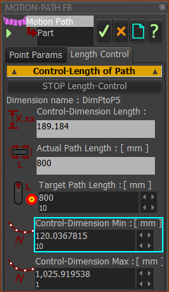
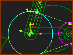
STEP 8: Edit the Target Path Length parameter

I want the Actual-Path-Length = 800mm.

Dimension name :   DIMPtoP5 - read-only

Control-Dimension Length = 205.184mm  - read-only

Actual Path Length = 830.283mm - read-only

Target Path Length = 830.2833223mm - read-write

Control-Dimension Min = 41.0367...mm - read-write

Control-Dimension Max = 1025.919...mm - read-write

We may need to narrow or widen the search space for the algorithm. I find the algorithm works best if I increase the Control-Dimension Min parameter.

1.Edit Control-Dimension Min and/or Control-Dimension Max by a small increment.  

2.Test that the Actual Path Length changes as you edit the Target Path Length.

3.Do 1 and 2 again, and again, to find the search space in which the Actual Path Length is equal to and updates with, the Target Path Length.

In the image to the left, I have INCREASED the Control-Dimension Minimum to 120.036... from 41.036...

4.Edit the Target-Path Length = 800mm = Actual Path Length

GST-T17-O2-Orbiting-Pulley-B007-small

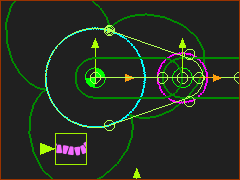
When the Target Path Length = 800mm,  you will see Trace-Point of the Motion-Point has three lobes.

Add a R-P-R dyad.

GST-T17-O2-Orbiting-Pulley-B008

Add a R-P-R  dyad


Remember: all dyads have 2 × Parts and 3 × Joints.

An R-P-R dyad has two Pin-Joints(R-×-R) and one Slide-Joint (×-P-×)


STEP 1: Add two Parts and two Pin-Joints:

1.Click Kinematic-elements toolbar > Add Part | Drag to add a Part.

2.Do again, to add a Part

Add Pin-Joint #1

3.Click Kinematic-elements toolbar > Add Pin-Joint | Click the start-Point of a Part and a Point at the center of the fixed Pulley.

The Select-Elements dialog opens because there is more than one Point at the center of the fixed Pulley.

In the Select-Elements dialog: CTRL+CLICK the:

start-Point of the new Part AND

Point with the Base-Part as an owner (parent).

Add Pin-Joint #2

4.Click Kinematic-elements toolbar > Add Pin-Joint | Click the start-Point of a Part and the Motion-Point on the Belt.

GST-T17-O2-Orbiting-Pulley-B009

STEP 2: Add a Slide-Joint between then CAD-Lines of the two new Parts.

Add Slide-Joint

1.Click Kinematic-elements toolbar > Add Slide-Joint

2.Click the CAD-Line along the centers of a new Part

3.Click the CAD-Line along the center of the other new Part.

The Slide-Joint will make the CAD-Lines in the two new Parts become collinear.

STEP 3: Cycle the mechanism (use the ALT+C keyboard combination).

You can see the Part that has the Pin-Joint with the center of the fixed Pulley moves 3x and dwell 3x, as the Crank  rotates 4x

Because the Motion-Point traces three lobes, the output Part is a three stop indexer.