Contact Stress: Calculated Fatigue Limit
The surface of cams wear, as do bearings and gears.
A Cam wears from micro-pitting because it is subject to a contact-stress as a Follower-Roller rolls over it. The cam would usually wear and eventually fail at the point that experiences the maximum contact-stress. Failure would be due to rolling contact fatigue. Like any machine part, the challenge is to make sure that the cam does not fail before the intended life of the machine.
Allowable Contact Stress
The Allowable Contact-Stress, is the upper limit of rolling contact stress that the cam steel can sustain, without failure by pitting for 1×Life*, with a reliability of 99%.
Failure from pitting is subjective and a source of considerable disagreement. One observer may say the cam has failed, and another says the cam is worn in.
One life is typically 5 × 10⁷ (50 million) stress cycles, but not always.
Note, for the internals of Follower-Rollers, 1 life is always 1 × 10⁶ ( 1 million) rotations.
For most cam materials, a life (in cycles) is considered to be the beginning of the endurance strength, its σ - N curve (also called its S-N curve).
We assume the cam fails at the point at which the contact-stress is a maximum.
We have seen that the contact-stress is a function of the contact-force, material properties, and the radii-of-curvature of both follower-profile and cam-profile.
Usually, both the contact-force and the radius-of-curvature of a cam-profile are different at each point along the Cam-Profile. Therefore, each point along the cam-profile experiences a different contact-stress. We must, therefore, calculate the contact-stress at all points along the cam-profile.
Hardness and Allowable Stress
Table 1- from ISO 6336 Part 5 - shows a first estimation of the Allowable Contact-Stress - for different Steel and Cast-Iron categories and heat-treatments.
You can see that the Allowable Contact-Stress is a function of the Steel Category, Steel Quality, and Surface-Hardness.
E.g. the Endurance Limit of a Normalized Low Carbon Steel with ME quality, that has a Brinell Hardness of 150HB is equal to 1.520HB+250 = 478MPa
The reliability is taken as 99%. That is to say, there is a probable risk of 1% that the cam will fail if subjected to a contact-stress equal to the stress in the table.
Depth of Hardness is also important because the maximum shear-stress is below the surface.
The lubrication mode is expected to be 'mixed', and the lubricant is 'clean'.
table 1 (from ISO 6336-5)
Steel / Cast Iron Categories * |
Material Type (and abbreviation) * |
Steel Quality ** |
Allowable Contact-Stress, MPa 99%, Rel. Z= 1 |
Hardness Range *** |
Example Steels NOT from ISO 6336 Please check steel and category before manufacture. |
|---|---|---|---|---|---|
Normalized Low Carbon Steels & Cast Steels (St (cast)) |
Wrought,normalized, Low Carbon Steels |
ML/MQ |
1.000HB + 190 |
110 - 210 HB |
St50.2, 1.0050, E295 St60-2, 1.0060, E335 St70-2, 1.0070, E360 |
ME |
1.520HB + 250 |
110 - 210 HB |
|||
Cast Steels |
ML/MQ |
0.986HB + 131 |
140 - 210 HB |
GE200, 1.0420 GE240, 1.0446 GE300, 1.0558 |
|
ME |
1.143HB + 237 |
140 - 210 HB |
|||
Cast Irons |
Black Malleable Cast Iron (pearlitic structure) (GTS (perl)) |
ML/MQ |
1.371HB + 143 |
135 - 250 HB |
EN-GJMB-350-10 : HB 150 EN-GJMB-500-5 : HB 165-215 EN-GJMB-600-2 : HB 195-245 EN-GJMB-700-2 : HB 240-290 |
ME |
1.333HB + 267 |
175 - 250 HB |
|||
Nodular Spheroidal Pearlitic Bainitic Ferritic Cast Iron (GGG (perl, bai, ferr)) |
ML/MQ |
1.434HB + 211 |
175 - 300 HB |
EN-GJS-400-15 : HB 135-180 EN-GJS-500-14 : HB 170-215 EN-GJS-600-10 : HB 190-230 EN-GJS-700-2 : HB 210-305 EN-GJS-800-2 : HB 240-335 EN-GJS-900-2 |
|
ME |
1.500HB + 250 |
200 - 300 HB |
|||
Cast Irons |
Grey Cast Irons (GG) |
ML/MQ |
1.033HB + 132 |
150 - 240 HB |
EN-GJL-200, GG20 EN-GJL-300, GG30 EN-GJL-350, GG35 EN-GJL-400, GG40 |
ME |
1.465HB + 122 |
175 - 275 HB |
|||
Through-Hardened Wrought Steels Nominally >0.2%C
|
Carbon Steels (V)
|
ML |
0.963HV+283 |
135 - 210 HV |
EN8 / 080M40. C40E, 1.1186 C45E, 1.1191, 1045,
|
MQ |
0.925HV+360 |
135 - 210 HV |
|||
ME |
0.838HV+432 |
135 - 210 HV |
|||
Alloy Steels |
ML |
1.313HV+188 |
200 - 360 HV |
EN19T/709M40T, 42CrMo5, 1.7225, 4140 |
|
MQ |
1.313HV+373 |
200 - 360 HV |
|||
ME |
2.213HV+260 |
200 - 390 HV |
|||
Through-Hardened Cast Steels Nominally > 0.2%C
|
Carbon Steels (Low to Medium) |
ML/MQ |
0.831HV+300 |
130 - 215 HV |
100Cr6 (52100, Ws#1.3505. SUJ2) |
ME |
0.951HV+345 |
130 - 215 HV |
|||
Alloy Steels |
ML/MQ |
1.276HV+298 |
200 - 360 HV |
G25CrMo4, G34CrMo4, G35CrNiMo6-6 G42CrMo4 :1.7231 |
|
ME |
1.350HV+356 |
200 - 360 HV |
|||
Case Hardened Wrought Steels |
< 0.25%C (Eh) |
ML |
1300 |
600 - 800 HV |
C14E/C10R/C15E/C15R/ 14NiCr4, 1.5752, EN36B/655M13 17Cr3 (1.7016, AISI 5115) 16MnCr5 (1.7131), 590M17 18CrMo4 20MnCr5 (1.7147) 15NiCr13 (1.5752) 17CrNi6-6 (1.5918) 18CrNiMo7-6 (1.6587) 20NiCrMo2-2, 22CrMoS3-5 18NiCrMo5 17NiCrMo6-4, EN36 - 1.5752 - 14NiCr4, SAE8620, 14NiCrMo13-4, AISI 9310, 1.6657 655M13 EN39B/835M15, 15NiCrMo16-5, SNCM815. |
MQ |
1500 |
660 - 800 HV |
|||
ME |
1650 |
660 - 800 HV (58-64HRC) |
|||
Flame or Induction Hardened Wrought or Cast Steels |
>0.25%C
(IF) |
ML MQ ME |
0.740HV+602 0.541HV+882 0.505HV+1013 |
485 - 615 HV 500 - 615 HV 500 - 615 HV |
34Cr4 (1.7033) (530M32) 41Cr4, 34CrNiMo6 43CrMo4(1.3563) |
Nitrided Wrought steels
|
Nitriding Steels |
ML |
1125 |
650 - 900 HV |
EN40B, EN41B, 31CrMo12, 42CrMoV12, 38CrAlMo 31CrMoV9. 905M39 |
MQ |
1250 |
650 - 900 HV |
|||
ME |
1450 |
650 - 900 HV |
|||
Through Hardened, Nitrided |
Through Hardening Steels |
ML |
788 |
450 - 650 HV |
32CrMoV13 |
MQ |
998 |
450 - 650 HV |
|||
ME |
1217 |
450 - 650 HV |
|||
Wrought Steels Nitro-Carburized |
Through Hardening Steels |
ML |
0.0HV + 650 |
300 - 650 HV |
100CrMnSi6-4 (CarboNitriding) |
MQ |
1.167HV + 425 |
300 - 450 HV |
|||
ME |
0.0HV + 950 |
450 - 650 HV |
|||
* Wrought Steels refers to all manufacturing processes that manipulate the shape of the steel without re-melting it. Hot and Cold rolling are the two common processes. Wire drawing, deep drawing, and extrusion are others. Cast Steel are poured into a mold to give their near final shape. ** ML, MQ, ME - consult with your steel re-seller, request the steel's data-sheet and specification. These specifications have demands on material quality, heat treatment processes, and the number and type of inclusions. ML : these steels have the least demanding specifications, least cost. MQ : greater demands to meet the specifications, experienced manufacturers can supply at moderate cost. ME : tightest controls, use when you need a high degree of operating reliability, greater cost. Refer to ISO 3663-Part 5 for more details of ML, MQ, ME steels qualities. *** HB - Brinell Hardness, HV - Vickers Hardness |
|||||
log(Z)-log(N) Plots to find N from Z (or inversely) Z from N
 vs Log(Z) plot. 3 Groups of Steels, 1 Group allows pittining.")
Log(N) vs Log(Z) plot.
3 Groups of Steels, 1 Group allows pittining.
Equations to calculate N from Z
Steel Group |
Range of Z values |
Limits of N |
Life, N before RCF* |
|---|---|---|---|
Steel Group 1: St, V, GGG (perl. bain.), Eh, IF ~15% pitting is allowed |
|
|
|
|
|
|
|
|
|
|
|
|
|
|
|
|
Infinite Life |
|
|
Steel Group 2 St,V, GGG (perl,bail)Eh, IF No pitting allowed |
|
Fatigue does not apply. |
|
|
|
|
|
|
|
|
|
|
Infinite Life |
|
|
Steel Group 3: GG, GGG(ferr), NT(nitr), NV(nitr.) |
|
Fatigue does not apply. |
|
|
|
|
|
|
|
|
|
|
Infinite Life |
|
|
Steel Group 4: NV (Nitrocar) |
|
Fatigue does not apply. |
|
|
|
|
|
|
|
|
|
|
Infinite Life |
|
Equations to calculate Z from N
Material Group |
Life in Cycles, N |
Z, from Life, N |
Range of Z values |
|---|---|---|---|
Steel Group 1: St, V, GGG (perl. bain.), Eh, IF (~15% pitting is allowed) |
|
|
|
|
|
|
|
|
|
|
|
|
|
|
|
|
|
|
|
Steel Group 2: St, V, GGG (perl. bain.), Eh, IF (No pitting allowed) |
|
|
|
|
|
|
|
|
|
|
|
|
|
|
|
Steel Group 3: GG, GGG(ferr), NT(nitr), NV(nitr.) |
|
|
|
|
|
|
|
|
|
|
|
|
|
|
|
Steel Group 4: NV (Nitrocar) |
|
|
|
|
|
|
|
|
|
|
|
|
|
|
You can use the equations above to find the required life-factor for a particular steel grade and number of cycles.
From the Life-Factor, for the steel, you can calculate the required hardness from the equation for Allowable Contact-Stress.
You can do the inverse calculation if you want to find the expected number of cycles to failure from a prescribed Life Factor.
The prescribed Life-Factor would be found from the ratio of Dynamic Contact-stress : Allowable Contact-Stress.
The Allowable-Contact-stress for one life is first established for the steel's category, quality, and hardness from the table above.
Typical Cam Material Classes and Heat Treatment
Cam Steels
There are many wrought steels, cast steels, and cast-irons that you can use to manufacture a cam. You must select the steel that can match the demands of your application.
The Allowable Contact STRESS of the steel is a function of:
•The steel's chemical composition: carbon, chromium, nickel molybdenum, vanadium, aluminum...
•Its manufacturing process: cast killed, wrought killed, continuously case, hot rolled, cold rolled, sintered, powder pressed, vacuum degassed, (VAR, ESR)
•Its heat-treatment: through-hardening, quenched and tempering, carburizing, nitriding, carbonitriding, ...
•Its quality standard: kiln quality, consistency of chemical composition, 'density' of foreign-body inclusions: MX - excellent, ME - better, MQ - standard, ML - lower than average
The steels used for industrial cams are Wrought-Steels, Cast Iron and Cast Steels, Powder-Metallurgy (PM), Tool Steels, and Maraging Steels.
By far the most common are wrought-steels.
Wrought-Steels
Wrought-Steel is the general term for a carbon and alloy steel that is mechanically worked into a bar, flat, or a forging. They are available in a wide range of sizes and grades. Wrought-Steels are either Through-Hardened (carbon content between 0.3 and 0.5%) or Surface-Hardened (carbon initially not exceeding 0.25%).
Surface-Hardened: steels have a relatively thin hard 'case', which results from processes such as carburizing, nitriding, carbonitriding.
Through-Hardened: steels that be considered to have the same hardness through its depth. However, in reality, they will also have hardness gradient.
Cast Irons and Cast Steels
Cast Irons (more than 2% carbon) and Cast Steels are poured into a mold that is near to the final shape of the cams. High volume engine cam-shaft are most often made this way. Cast-Iron would normally be a 'chilled' cast-iron as this gives an extremely high surface hardness that will wear.
In the fast majority of cases, the cam is manufactured from a ferrous metal - iron and steel, cast and wrought.
There are a number of classes of ferrous metals with which we can manufacture the cam:
'Soft' or Hard' Cams Cast Irons or Cast Steels that are not normalized and tempered. Hardness in the range of 100-360HB. Surface Hardened Cams These cams use Direct Hardening Steels. The carbon content is the range of 0.3 to 0.45%, with and without alloying elements, typically Chromium, Nickel, Molybdenum, Vanadium and Aluminum. Examples steels are: C45E (Ck45), 42CrMoV. Direct Hardening is by Flame or Induction Heating, followed by Quenching and Tempering. Hardness in the range of 550-650HV. Compared to case-carbonizing, there is less distortion with flame and induction hardening. Case Carburized Surface Hardened Cams The carbon content of plain and alloy steels is increased by carbonization at 850-950ºC, to achieve a carbon content of 0.7% to 0.9% in the outer case of the cam. After quenching and tempering, the surface hardness can be in the range of 650-750HV. Case Hardening processes include Carburzing and Carbonitriding (not Nitriding) Example steels are: 18CrNiMo7-6, 16MnCr5. A minimum case depth will be a function of the size of the cam and the depth of maximum shear stress. Nitrided Cams Nitriding of plain carbon, alloy and nitriding steels is carried out at 500-550ºC with ammonia for gas nitriding to form hard carbides close to the surface. Because the temperature is low and there is no need for quenching, there is much less distortion, if any, of the cam. This may mean there is no need for grinding the surface after heat treatment. The hard case, of up to 850HV, is relatively shallow. Example Steels are: 32AlCrMo4, 34CrAl6, 31CrMoV9, Nitrided surfaces often have lower coefficient-of-friction than other surfaces and also there is some corrosion resistance. |
Benefits of the different Heat-Treatment Processes
Carburizing Hard, highly wear-resistant surface (medium case depths); excellent capacity for contact load; good bending fatigue strength; good resistance to seizure; excellent freedom from quench cracking; low-to-medium cost steels required; high capital investment required Carbonitriding Hard, highly wear-resistant surface (shallow case depths); fair capacity for contact load; good bending fatigue strength; good resistance to seizure; good dimensional control possible; excellent freedom from quench cracking; low-cost steels usually satisfactory; medium capital investment required; improved salt corrosion resistance Nitriding Hard, highly wear-resistant surface (shallow case depths); fair capacity for contact load; good bending fatigue strength; excellent resistance to seizure; excellent dimensional control possible; good freedom from quench cracking (during pretreatment); medium-to-high-cost steels required; medium capital investment required; improved salt corrosion resistance. The depth of hardness with Gas-Nitriding is a function of the hours and the steel.  Note: Copyright lost - please email with your preferred action. Induction hardening Hard, highly wear-resistant surface (deep case depths); good capacity for contact load; good bending fatigue strength; fair resistance to seizure; fair dimensional control possible; fair freedom from quench cracking; low-cost steels usually satisfactory; medium capital investment required Flame hardening Hard, highly wear-resistant surface (deep case depths); good capacity for contact load; good bending fatigue strength; fair resistance to seizure; fair dimensional control possible; fair freedom from quench cracking; low-cost steels usually satisfactory; low capital investment required |
Allowable Contact Stress and Surface Hardness
|
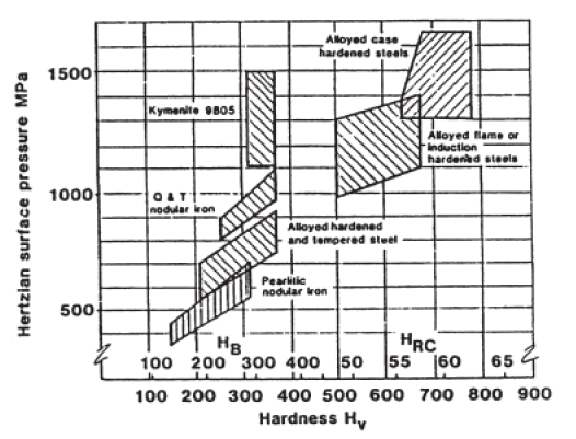
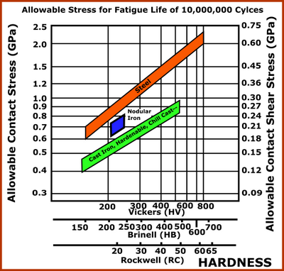
Rules of Thumb •Through Hardened Steels; Range of Brinell Hardness; HB = 180 – 400, Grade of Steel: 'Grade 1, (ME,MQ); Reliability, 99% Statistical Reliability; Number of Cycles: 1x10⁷ •Allowable Contact Stress ~ 2.41HB +237 (MPa ) •If you want 10 - 100 million cycles than increase the HB Hardness by 15 –20%. The image shows typical Allowable Maximum Contact Stress and Allowable Maximum Contact Shear Stress values against Brinell, Vickers and Rockwell 'C' Hardness Scales.) The values assume the Follower-Roller rolls in clean oil. |
Case Hardness, Case Depth, Core Strength
 Importance of Depth of Hardening / Core Strength and Depth of Maximum Shear Stress. |
The depth of is not important with homogenous materials. For example, a Through-Hardened steel. However, with case-hardened and surface hardened cams, it is possible that the case is strong enough, but the core is not, and vice versa. Case: < Allowable Shear Stress (function of material and hardness ) Core: < Allowable Shear Stress (function of material and hardness) Case Depth For Carburized and Carbonitrided Cams, the Case Depth is the depth at which the hardness is greater than 550HV (-see also Definitions of Case-Depth, below) The depth of Maximum Shear-Stress, , should be compared to the Case-Depth from the surface As a rule of thumb, Case Depth > assuming that Maximum Shear Stress will not damage the steel when the Hardness is 550HV. Core Crushing If the Hardness reduces rapidly after the Case-Depth, it is possible to Crush the Core when the Shear or a Principal Stress is greater than the steel strength. Hardness rapidly falls with Induction and Flame Hardening. Definitions of Case Depth.Effective Case Depth (CHD) The definition of Effective Case Depth is a dependent on the heat treatment process. 1.Carburized or Carbonitrided Cams (EN ISO 2639) Hardness Limit = 550 HV. CHD (Eht) = Distance from surface to a point where the hardness is 550 HV. Hardness tends to gradually drop off, depending in the core hardness. 2.Induction or Flame Hardened Cams (EN 10328, ISO 3754) Hardness Limit = 80% x (Minimum) surface hardness. CHD (Rht) = Distance from surface to point where hardness is 80% of the (minimum) surface hardness. Hardness tends to drop rapidly at a depth slightly greater than this limit. 3.Nitrided Cams (DIN 50190-3) Hardness Limit = Core Hardness + 50 HV. CHD (Nht, NCD) = (Max.) Distance from the surface to the point where hardness is 50HV above core hardness. Nitrided cams have a relatively shallow case depth, but a gradual hardness gradient. Total Case Depth The depth at which the hardness becomes the same as the core hardness. |
Modification Factors:
The allowable contact-stress is often modified - in the same way as the Follower-Roller life is modified - with modification factors.
Metallurgy
The allowable stress numbers are a function of melting, casting, forging and heat treating practice. Hardness, tensile strength, micro-structure and cleanliness are some criteria for determining allowable stress numbers. Allowable stress numbers in this standard are based on 107 cycles, 99 percent reliability and unidirectional loading.
Residual-Stresses
Any material in which the case is harder than the core is likely to have residual stresses. If properly managed, these stresses are compressive at the surface and should enhance the performance of the cam. Shot-peening, case-carburizing, nitriding, and induction hardening are common methods of inducing compressive pre-stress in the surface. Grinding after heat treatment may reduce the residual compressive stresses. Care must be taken to prevent excessive reduction in hardness and changes in microstructure during the grinding process.
Life Factor
When the contact stress is not an alternatively, Table 2, shows the allowable stress for 10,000,000 ;100,000, and 1000 cycles.
Table 2
|
|
|
|
Alloyed case hardened steels (surface hardness 58-63 HRC): |
|||
- of specially approved high grade: |
1650 |
2500 |
3100 |
- of normal grade: |
1500 |
2400 |
3100 |
Nitrided steel, gas nitrided - surface hardness 700-800 HV () |
1250 |
|
|
Alloyed Quenched and Tempered steel, bath or gas nitrided -surface hardness 500-700HV |
1000 |
|
|
Alloyed flame or induction hardened steel - surface hardness 500 - 650 HV |
0.75.HV + 750 |
|
4.5 × HV |
Alloyed quenched and tempered steel: |
1.4.HV + 350 |
|
4.5 × HV |
Carbon Steel: |
1.5.HV + 250 |
|
|
These values refer to wrought steels, hot-rolled or forged. For cast steel, reduce by 15%. |
|||