Lubrication for Cams and Gears
Reasons to lubricate the Cam-Profile and Follower-Roller
1.Reduce wear
2.Increase the life of the Cam-Profile and the Follower-Roller
3.Reduce the temperature rise of the gears
4.Reduce scuffing between the gears
5.Remove contaminants
6.Reduce noise
Film Thickness Ratio
Film Thickness Ratio is conceptually simple.
Film Thickness Ratio, :
= Lubricant Film Thickness
= Combined Cam and Follower Surface Roughness
Film Thickness Ratio |
Failure Characteristic |
|
Minimal wear and long life can be expected. |
|
Surface glazing may occur and there is a risk of sub-surface originated pitting. |
|
Surface distress and pitting may occur , but is usually avoided. |
|
Surface scoring, smearing or deformation occurs at the cam surface and is followed by wear. |
Comparison of Film Thickness with typical contaminants  |
|
 h, Lubricant Film Thickness
Formula for Film Thickness
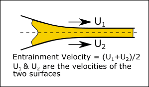
Entrainment Velocity,
Equivalent Radius of Curvature of Cam and Follower, Rx
Dynamic Viscosity, and Kinematic Viscosity,
|
||||||||||||||||||||||||||||||||

Combined Surface Roughness
The combined surface roughness is derived from the roughness of the cam and the Follower-Roller:
The cam's roughness, ( ) and Follower-Roller's roughness, () are the Root-Mean-Square (RMS) roughness values. To approximately convert to Root-Mean-Square roughness, , from Center-Line-Average roughness, , use:
Note: , (F. Sadeghi, in Tribology and Dynamics of Engine and Powertrain, 2010) |
Regime of Lubrication
There are four different modes of lubrication that can be identified for self pressure generating lubricated contacts.
|
REGIME 1: Hydrodynamic Lubrication : occurs mainly in Plain Bearings.
The load carrying surfaces are separated by a relatively thick film of lubricant. Metal-to-metal contact does not occur. The lubricant pressure is self generated by the moving surfaces drawing the lubricant into the wedge formed by the bounding surfaces at a high enough velocity to generate the pressure to completely separate the surfaces and support the applied load. |
||||||
REGIME 2: Elastohydrodynamic Boundary Lubrication : common in Gears and Bearings.
The lubricant is introduced, entrained and maintained into the contact area by the relative motion of the cam and follower Its viscosity increases significantly due to the high pressure. The load and pressure are high enough to elastically deflect the contact area (metal actually moves). This helps to make the contact more conformal, and will assist lubricant entrapment. |
|||||||
|
REGIME 3: Mixed-Boundary-Lubrication : common for cam sliding and rolling Follower-Rollers.
Partial or mixed lubrication regime deals with the condition when the speed is low, the load is high or the temperature is sufficiently large to significantly reduce lubricant viscosity – when any of these conditions occur, the tallest asperities of the bounding surfaces will protrude through the film and occasionally come in contact. The load is partly supported by an Elasto-hydrodynamic Film and partly by Solid Contact between the high spots of the cam and follower surfaces. Some surface 'glazing' may occur (polishing). |
||||||
|
REGIME 4: Boundary-Lubrication
Boundary lubrication is the condition when the oil film is insignificant and there is asperity contact. The load is not supported by the oil. Rather, there is solid contact between the surfaces. The physical and chemical properties of the films at the contacting surfaces become important, while the properties of the bulk oil are not. EP (Extreme Pressure) Additives (see below: AW and EP Additives should be in the lubrication. The EP additives adhere to the surfaces or chemically modified them. The solid-film will also have low shear-strength. Smearing and wear are much more likely with boundary lubrication. |
||||||
AW (anti-wear) and EP (extreme-pressure) Additives In practice, a Cam-Profile and Follower-Roller will often have an oil-film thickness below the optimum. In this condition, the hydrodynamic film is not developed and a mixed or boundary condition is present, the asperities on the interacting surfaces start to contact and the temperature rises. This is where AW and EP Additives may be used. AW and EP additives react with the surfaces forming tribolayers that prevent direct contact between the sliding surfaces. Usually, anti-wear agents have a lower activation temperature than the extreme-pressure ones. The distinction between anti-wear and extreme-pressure additives is not very clear. Some are classified as AW in one application and EP in another, and some have both functions. AW additives are designed to deposit surface films under moderate contact pressures whereas EP additives are much more reactive and are used when the contact pressures are very high in order to prevent modes of failure like scuffing. Temperature activated EP additives The three most common temperature activated EP additives are chlorine, phosphorus and sulphur. They are activated by reacting with the metal surface when the temperature is elevated. The chemical reaction between the EP additive and the metal surface forms a new compound that acts as a barrier to reduce friction, wear and the possibility of welding. These EP additives are effective over different temperature ranges.
Non-temperature activated EP additives The non-temperature dependent overbased sulphonate EP additives operate by a different mechanism. Although the film formation is similar to the temperature dependent additives. The sulphonates contain a colloidal carbonate salt dispersed within the overbased sulfonate and during the interaction with iron the colloidal carbonate forms a film that can act as a barrier between the metal surfaces. More technically: Common AW and EP additives are organo-sulfur and organo-phosphorus compounds; organic polysulfides, phosphates dithiophosphates and dithiocarbamates. In the 1930’, zinc dialkydithiophosphates (ZDDP) was introduced initially to prevent bearing corrosion. However, it was found to have good anti-oxidant and anti-wear abilities. |
|||||||


Striebeck Curve
Striebeck Curve shows Wear; Film Thickness; Coefficient-of-Friction as a function of the Viscosity, Velocity, Load

Striebeck Curve
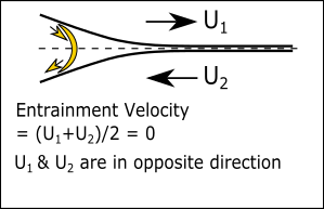
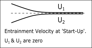
Elastohydrodynamic Boundary Lubrication, because the relative speeds might reduce to zero, and even become negative (e.g., a Flat-faced Followers) the lubricant entrainment will stop and the pressure will drop. At this point in the cycle, only Mixed Boundary Lubrication will exist.
Obviously, if a cam and follower are to be run without lubricant – especially a sliding contact follower - then wear and life depend on the material properties, especially its scuffing resistance and self lubricating properties.
Cam systems without lubricant are usually suitable for light loads or speeds. In this case, cams with followers-rollers, rather than sliding flat-faced followers, are preferred.
When a design choice must be made for the surface finish and whether to use anti-wear additives in the lubricant, it is necessary to make an estimate of the film thickness between the cam and follower at each point in the machine cycle.
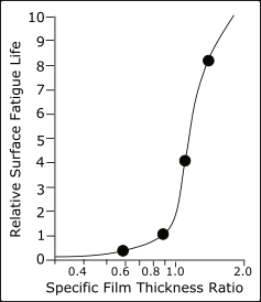
Fatigue Life as a function of Film Thickness Ratio
|
There is a rapid increase in cam and Follower-Roller fatigue life if the Film Thickness Ratio becomes greater the 1. What is Beta ( β ) Ratio? Beta ratio (ß) is a formula used to calculate the filtration efficiency of a particular fluid filter using base-data obtained from multi-pass testing. In a multi-pass test, fluid is continuously injected with a uniform amount of contaminant (i.e., ISO medium test dust), then pumped through the filter unit being tested. Filter efficiency is determined by monitoring oil contamination levels upstream and downstream of the test filter at specific times. An automatic particle counter is used to determine the contamination level. Through this process an upstream to downstream particle count ratio is developed, known as the beta ratio. The formula used to calculate the beta ratio is: β(x)= particle count in upstream oil / particle count in downstream oil. E.g. : β4(x)= 200 200 times fewer particles, size of 4μm, downstream than there are upstream of a filter. This means it is 99.5% efficient. |