Dynamic Response: Vibration, Period-Ratio, Damping and Backlash
This topic discusses vibration - which we call the Dynamic-Response - when a motion-law moves a mechanical system.
When a cam moves a payload, the motion-law is the input, which we can also call the motion-command. The motion of the follower is the output, which we call the motion-response. The motion-response of the payload at the output is not exactly equal to the motion-command at the input. The motion-response takes the form of a vibration of approximately constant frequency, but of varying amplitude, superimposed on the motion-command at the input. A cam mechanism can be represented by the simple model represented, as in the image below. There is a: •Rotating Cam and Translating Follower •Follower-Roller, of negligible mass •Payload, with mass, () •Spring, with stiffness, , between the Cam and Payload. The spring represents the output transmission, and its stiffness. |
 The image shows the start of the Command Motion-Law from the Cam, and an exaggerated Payload Motion Response |
Motion-Response of the Payload to the Motion-Command: •the Follower-Roller begins to move. •the Payload begins to accelerate with an acceleration that is proportional to the deflection of the spring and the spring stiffness. •The spring compresses by an amount proportional to its stiffness, . •The motion of the Payload lags that of the motion of the Follower-Roller until the force on the Payload from the Spring gives sufficient acceleration to it such that the velocity of the Payload is greater than that of the velocity of the Follower-Roller. •Then, the spring begins to expand again. The spring expands until it matches its original length and the displacement of the Payload is equal to the displacement of the Follower-Roller. •However, at that instant, the Payload is moving faster than the Follower-Roller. •The maximum displacement of the Payload becomes greater than the displacement of the Follower-Roller. As the spring continues to expand, the Payload's velocity decreases, relative to that of the Follower-Roller, until their velocities are the same. •The velocity continues to decrease until the displacement of the Payload and Follower-Roller become the same, again. A similar cycle of events occurs again and again, throughout the stroke, so that the Payload motion has an oscillation of varying amplitude that is superimposed on (added to) the motion of the Follower-Roller. |
Natural-Frequency and Period-Ratio
For a one degree-of-freedom cam system, as described above, we can calculate the natural-frequency. |
||
Linear System |
Rotary System |
|
|
|
Natural Angular Frequency |
|
|
Natural Frequency |
|
|
time-period |
|
Machine Cycle Frequency |
|
|
Segment Period, |
|
Period Ratio : |
|
|
= Natural Angular Frequency = Natural Frequency = Natural Period - time for 1 cycle in natural-frequency = Linear Stiffness = Mass = Torsional Stiffness = Mass Moment of Inertia = Machine-Speed, = degrees of shortest motion segment from 360 in the machine-cycle = Segment-Period time for shortest segment in the motion-cycle = Period-Ratio - the ratio of segment period to natural-period |
||
Note: To prevent confusion with the term oscillation of a swinging-arm follower, we refer to the dynamic-response as a vibration and not an oscillation. Period-Ratio () is the ratio of the period of the shortest segment (stroke time) to the period of the natural vibration (time for one vibration cycle) in the dynamic-response. Period-Ratio is the most important parameter to estimate the peak load on a cam and the maximum possible machine speed. The displacement-amplitude of the dynamic-response is much less than that illustrated in the image at the top of this topic. It is often difficult to see. However, the acceleration-amplitude of the dynamic-response is a large percentage of the total acceleration. Since inertia-force is proportional to acceleration, the dynamic-response contributes to a large percentage of the total inertia-force. The frequency of the dynamic-response is the natural-frequency of the mass-spring system. The natural-frequency can be measured with a sensor, or estimated with reasonable accuracy from the mass and linear-stiffness (or in the case of rotary systems, from the mass moment-of-inertia and torsional-rigidity) of the mechanism. The nature of the dynamic-response, its acceleration-amplitude in particular, is a function of the motion-law, the duration (period) of the motion segment, the mass (or mass moment-of-inertia) and the linear-stiffness (or torsional-rigidity) of the mechanism and payload. Equivalent Machine Speed. We can use Period-Ratio as an equivalent machine-speed. High-speed applications are those with a LOW Period-Ratio - e.g. less than 8. Slow-speed applications are those with a HIGH Period-Ratio e.g. more than 20. The choice of motion-law is less critical with slow-speed applications. Most cam mechanisms in modern industrial machinery run with a Period-Ratio less than 20. There are few successful cam-mechanisms with a Period-Ratio that is less than 5. |
||
EXAMPLES
Modified-Trapezoidal (Mod-Trap), Cycloidal, Modified-Sinusoid (Mod-Sine) - Acceleration Plots
 Mod-Trap Response with High and Low Period Ratio |
 Cycloidal Response with High and Low Period Ratio |
 Mod-Sine Response with High and Low Period Ratio |
The images show the Dynamic-Response and Residual-Vibration with: Good Output Transmission = high ratio of Rigidity : Inertia = high value of Period Ratio Bad Output Transmission = low ratio of Rigidity : Inertia = low value of Period Ratio The three diagrams above show the dynamic-response and residual vibration of a mechanism with three different motion-laws and two different Period-Ratios. They show the nominal-acceleration of the motion-law and the acceleration-response plotted against time for one motion-period and one dwell period. •Diagrams at the top: Period-Ratio = 13.5 - good (rigid) output transmission •Diagrams at the bottom: Period-Ratio = 3.25 = bad (soft) output transmission. The rigidity of the output transmission is the difference between the top and bottom. (Alternatively, the bottom diagrams might be the same transmission rigidity but operating 13.5÷3.25 times faster). A number of important points are illustrated by these diagrams: 1.The amplitude of the dynamic-response of all three motion-laws is low when the Period-Ratio is high. 2.The amplitude of the dynamic-response of all three motion-laws is high when the Period-Ratio is low. The amplitude of the acceleration response may be >2× the nominal maximum of the motion-law. 3.The vibration in the dwell-period (called the Residual-Vibration) may be damped down to zero before the next segment period if there is some friction, the vibration-amplitude is low (good transmission). The residual-vibration of a bad transmission may not be damped out quickly enough and could make the dynamic response of the subsequent motion worse still. 4.If the transmissions are good, the Mod-Trap motion has a peak acceleration less than either the Mod-Sine or Cycloidal, by virtue of its lower maximum nominal-acceleration. If transmissions are bad, however, the Mod-Sine is better than Mod-Trap (note the negative peak of the Mod-Trap) and Cycloidal is better than the Mod-Sine, especially as regards the residual vibration. All three motion-laws shown are considered to be good laws for high-speed mechanisms - they have finite jerk throughout. |
||
Parabolic and Simple Harmonic Motion
 Simple Harmonic Motion Response with High and Low Period Ratio |
 Parabolic Response with High and Low Period Ratio |
For comparison, two images above show the dynamic response of the Constant Acceleration / Deceleration and the Simple Harmonic motion-laws. These motion-laws were popular because of their simple formulation, their low peak nominal acceleration and the apparently smooth profiles that they produced. However, they do not give a satisfactory dynamic response, even at low speed and even with a good transmission design. Both motion-laws have a step-change - that is, a discontinuity - in the acceleration profiles. The step in the acceleration shocks the mechanical system, and incites the vibration in it much more than those motion-laws that do not have a step-change in acceleration. The maximum acceleration of the dynamic-response are much the same for both motion-laws at all Period-Ratios. This is because the vibrations are caused mainly by the step-change in acceleration. |
|
Torsion Factor
It is possible to estimate the Maximum Torque, to include the vibration superimposed on the nominal torque, at the mechanism design stage if the Motion-Law is known and you can estimate the Period-Ratio. Torsion Factor, , is the ratio of the actual maximum torque (or acceleration) to the nominal maximum torque (or acceleration). It assumes it is an undamped system with a wholly inertial load - spring, frictional, damping, gravitational forces, and others, are all zero. Note: The term Torsion-Factor is historical. It was first used with indexing mechanisms where the input and output transmissions were always rotary, hence torsion. Torsion Factor Equation The Torsion-Factor Equation estimates the ratio of peak (or actual) acceleration to nominal (or motion-law) acceleration. When a cam-mechanism has the same motion-law, its Torsion-Factor is dependent only on its Period-Ratio. Curves have been plotted of Torsion-Factor, , against Period-Ratio, n, for the SCCA family of Motion-Laws. The Torsion-Factor is empirically given by the equation: |
|||||||||||||||||||||||||||||||||||||||||||||||||
|
- Constants for each motion-law |
||||||||||||||||||||||||||||||||||||||||||||||||
; Period Ratio, |
|||||||||||||||||||||||||||||||||||||||||||||||||
|
|||||||||||||||||||||||||||||||||||||||||||||||||
Notes: Parabolic Motion-Law: Torsion-Factor, at all Period-Ratios. Thus, it is a poor motion for any application, even slow speed, with good transmissions. Simple Harmonic Motion-Law: Torsion-Factor, at all Period-Ratios when preceded and followed by a Dwell. Therefore, it is not as good as the Mod-Trap, Mod-Sine, or Cycloidal for many applications. The high Torsion-Factor of Simple Harmonic Motion is due to the sudden change of acceleration at the start and end of the Motion-Law, when you use this motion-law between dwell segments. In applications where there are no dwells, and the acceleration is continuous, then Simple Harmonic Motion is the best for minimum vibration. In many cases, a low value of Jerk at Cross-Over (transition between acceleration and deceleration) of Simple-Harmonic-Motion also reduces the effects of backlash in the system. |
|||||||||||||||||||||||||||||||||||||||||||||||||
Residual Vibration
Above, we have seen that in most cases there is a residual vibration at the end of the motion, whose amplitude may be considerable. It is of course a continuation of the vibration that has built up during the motion period. However, it is possible for the residual vibration amplitude to be very small or zero, even though the in-motion amplitude might be very large. It depends on exactly where in a vibration cycle the motion finishes. Slight variations in the value of Period-Ratio, n, cam make an enormous difference to the residual vibration amplitude. The dynamic responses of two similar mechanisms are shown below. A high speed application, low Period-Ratio, has been chosen for the clarity. |
 Possible REDUCTION of Residual Vibration with small INCREASE in speed, with certain Period Ratios |
The only difference between the two mechanisms is the rigidity of the input transmission. There is a slightly different Period-Ratio in each case. The vibration response of the design on the left side has a Period-Ratio, n=5.25. The one on the right has a Period-Ratio, n= 4.5. Surprisingly, there is an extremely large residual vibration with the better Period-Ratio, while the worse Period-Ratio produced practically no residual vibration. It is important to note that no damping of any kind was used: the zero residual vibration is entirely due to the vibratory state of the mechanism at the beginning of the dwell period. The in-motion vibration is the same for both mechanisms and is of similar amplitude to the worst residual vibration. The value of Period-Ratio, n, can seldom be predicted exactly because of unforeseen errors in mass and rigidity. In any case, there is a great variation in speed, and therefore, period-ratio, during the run up to speed, and during the machine shutting down. Although residual vibration may be undesirable for many reasons, it is not in itself the criterion for estimating the load capacity of a cam system. The peak load on the system is always at the peak acceleration(positive or negative) of the in-motion vibration cycle. |
Damping
Damping absorbs energy. It has the effect of reducing, and possibly eliminating vibration. There are three basic kinds of damping that apply to cam and follower systems: •Viscous Damping : force that is proportional to velocity. E,g. Lubrication. •Hysteresis Damping : more energy stresses a material than the amount of energy that is returned to the system when the stress is released. •Constant, or Coulomb Damping (Friction Damping) : approximately a force proportional to the Normal Force that opposes the motion. We find all are present to some extent in industrial machines. But, the first two, viscous and hysteresis, are usually so low as to have little or no effect on vibration. Why? It is futile to increase viscous damping deliberately to dissipate vibration energy. To damp vibration near to the beginning or the end of the motion where the nominal velocity is very low, or in the dwell period, the damping factor must be very high. In that case, energy will be wasted in the central, high-speed, period of the motion. Only that part of the viscous damping force that is related to the change of velocity contributes to the reduction of vibration, and the relative change of velocity due to vibration, even during the motion period is quite small. A constant friction is often present in the form of friction in bearings, slide-ways etc. This force, however, has no damping effect at all unless the motion changes its direction. Such reversals do not take place until the vibration velocity exceeds the nominal follower velocity, that is during and just before the dwell period. This form of damping is very effective in dissipating residual vibration, except in very high speed applications, but does not affect the majority of in-motion vibrations at all. If it is important in a particular application to eliminate vibration then the deliberate introduction of constant friction damping may be justified. However, it has the drawback that the follower can come to rest slightly out of position in the dwell period, where it is being held by the friction force in a strained condition, either under-shooting or over-shooting its target. |
Selecting a Motion-Law based on Peak Force/Load Criterion
 Ca*Ct vs Period-Ratio for Mod-Trap, Mod-Sine and Cycloidal Motion-Laws |
If peak load is used as a criterion for selecting a motion-law (although it is by no means the only criterion), then the product of Torsion Factor and Coefficient of Acceleration (= ), which is the Actual Maximum Inertia Load, identifies the best cam for a particular range of Period-Ratios. Using the equation of Torsion-Factor, with the associated table of parameters for each motion-law, we can plot: • against Period-Ratio, ... for Mod-Trap, Mod-Sine and Cycloidal motion-laws. We can use the plot to see which motion-laws is best as a function of Period-Ratio. The comparison is only valid where there is good input transmission and the peak load is mainly an inertia load. In these circumstance it can be seen that the •Mod-Trap is the best choice for a Period-Ratio better than 6.4 •Cycloidal is best below 6.4. However, Mod-Sine is by far the most useful of the three motion-laws because, although it produces a slightly higher peak load than Mod-Trap, it is also very much more tolerant to an elastic input transmission (low Period Ratio). The transmission systems of most industrial cams are such as to benefit from the use of the Mod-Sine motion-law in preference to the Mod-Trap. Nevertheless, there is a positive advantage to use the Cycloidal for systems with a low Period-Ratio. Mod-Sine is recommended as the first choice for Period-Ratios greater than 6.4, and Cycloidal for ratios less than 6.4. |
Backlash
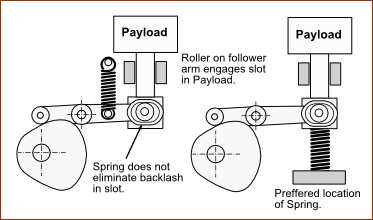
The total backlash in a cam mechanism is the sum of all clearances, play, or slack in the input and output transmissions (adjusted, if necessary, by gearing ratios), a Groove-Cam, and Follower-Roller. Typical examples are: slack chain drives, gear tooth clearances, oversize enclosed cam-tracks and worn follower roller bearings. There are many others. Any backlash, between the cam and follower or between any two force-transmitting components in the cam system gives rise to a shock load when there is a reversal of force or torque. Backlash can be often be eliminated by applying sufficient external force with a spring or the payload weight, or even a friction force, to ensure that there is not a force reversal at the operating speed. Spring loaded, open cam track cam systems are quite common, but to be fully effective in eliminating backlash the spring must be applied not just to the follower but at a point in the output transmission that closes ALL of the significant clearances. This is illustrated in the image. |
||||||||||||
|
||||||||||||
|
||||||||||||
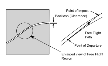
When the direction of force reverses, typically at the cross-over in high inertia applications, there is a moment when the payload is in free-flight after losing contact with the 'positive force surface' and before making contact with the 'negative force surface'. The magnitude of the force in making contact - the impact force - is related to the impact velocity of the contact surfaces. This, in turn, is related to the values of cam acceleration and jerk at this point in the motion. The process can be seen in the simplified and exaggerated image. All of the cumulative backlash in system is represented by the separation of the two cam profiles and the payload is represented at a concentrated point running along the profiles. The lower profile can only exert a positive contact force on the payload and the upper profile only a negative force. It is assumed for the purpose of this description that dynamic response vibration and any other detrimental effects are not significant compared with the impact force. The payload departs from the lower profile when its contact force becomes zero: this is when the inertia force due to the profile deceleration is about to exceed any other retarding force on the payload, such as friction, gravity. From this point on, the payload takes a free-flight path with a natural deceleration which is determined by external forces - such as friction - until it makes contact with the upper profile. It strikes the profile with an impact velocity - which is the difference between the free-flight velocity and the profile velocity. The free-flight is now a little slower that at the point of departure (due to its deceleration), and the profile velocity is even slower because the impact point is a little further along the profile (past the point of maximum profile velocity). It is obvious from the image that the Follower-Roller separates and impacts in the deceleration phase of the motion and are separated by a time and distance very much dependent on the amount of backlash. How far into the declaration phase that these events occur is dependent on the magnitude of the external force in relation to the payload inertia force. In practice, the possible range of impact positions is fairly wide and occurs just after the nominal cross-over point of the motion. To minimize the backlash impact force, it is necessary to have a motion-law with a low value of acceleration for a long period near the middle of the motion. In general, this condition is fulfilled by motions that have a low jerk at cross-over. The best 'low-impact' Traditional Motion-Law is Simple Harmonic, but special low impact motion-laws have been developed which improve on this. Here again, the Mod-Sine offers a very good compromise: it has a lower jerk at cross-over than the Mod-Trap, or Cycloidal and a much better dynamic response vibration than Simple Harmonic. |
||||||||||||
It is difficult to quantify the impact effect of backlash in all circumstances, but an attempt is made here to indicate its importance in certain cases. To take account of various sizes, speeds and loads of all kinds of cam mechanisms it is convenient to normalize the variables on the same basis as: |
||||||||||||
|
- = Normalized backlash as a ratio of the output stroke |
|||||||||||
|
- = Normalized 'natural' deceleration, due to friction, not the motion |
|||||||||||
|
- = Real natural deceleration of the payload - from linear model |
|||||||||||
|
- = Real natural deceleration of the payload - from angular model |
|||||||||||
|
- = Normalized impact velocity from real impact velocity and stroke |
|||||||||||
The natural deceleration of the payload in free-flight can vary between zero (at cross-over) and the maximum deceleration of the motion-law: a higher deceleration would maintain contact with the positive force cam surface! The higher the natural deceleration, the lower the impact velocity. For any cam-law, a graph can be constructed to show how the normalized impact velocity varies with backlash and natural deceleration. All the motion-laws have similar impact velocities when the natural deceleration is zero and the backlash is large. The are considerable differences in impact velocities between motion-laws when the natural deceleration is medium to high. The motion-laws with zero jerk at cross-over (Simple-Harmonic and Mod-Sine) are better than the others at low values of backlash - the sort of backlash values likely to occur in practice. For very high speed mechanisms, the value of the normalized natural deceleration must be low, because it is proportional to the square of the motion period, T , which can be very small. Also, the backlash is in practice kept to a minimum by precision manufacture. Of the Traditional Motion-Laws, Modified-Sinusoid (Mod-Sine) gives a good compromise. A shock vibration is set up on impact, the amplitude of which depends on the impact velocity and the natural frequency of the system. We have already seen that natural frequency, f , can be calculated from the rigidity and stiffness of the system and the payload mass or inertia. The impact force or torque at the cam to follower contact point is given by : |
||||||||||||
|
|
- natural frequency |
||||||||||
|
-inertia of the payload |
|||||||||||
|
- mass of payload |
|||||||||||
|
- angular rigidity of a rotary transmission |
|||||||||||
|
- linear stiffness of a linear transmission |
|||||||||||
|
- peak shock force in the direction of the follower motion |
|||||||||||
|
- peak shock torque |
|||||||||||
|
- impact velocity |
|||||||||||
Note, see above for , , In summary, the best way to minimize the detrimental effects of dynamic response from backlash is to : •use a “good” motion-law - for example Modified Sinusoid, Cycloidal •ensure that the input and output transmissions are rigid / stiff •ensure that the input and output transmissions are free of backlash |
||||||||||||