Before and After: Graphic-Area & Kinematics-Tree

<< Click to Display Table of Contents >>

Navigation:  Getting Started Tutorials - MechDesigner > Tutorial 14: Gear-Pairs / Rack-Pinions >

Before and After: Graphic-Area & Kinematics-Tree

Before and After: Graphic-Area and Kinematics-Tree

Summary

Add Gear-Pair removes one degree-of-freedom from a rotating-Part.

Before you do Add Gear-Pair

A rotating Green Part

A freely, rotating Blue Part

A Green Line that joins, with Pin-Joints at its start-Point and its end-Point, the Green Part and the Blue Part

After you do Add Gear-Pair

One Green Part that is the Driving Gear

One Green Part that is the Driven Gear - this is the Geared-Rocker in the Kinematics-Tree.

One Green Part that joins the two Gears.


Before and after Add Gear-Pair - Details

Basic Preparation for Add Gear-Pair

Basic Preparation for Add Gear-Pair

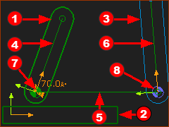
Before Add Gear-Pair.

Three (3) PartsRed-14-1bRed-14-2Red-14-3:

otwo(2) (moving or stationary) kinematically-defined Parts (Green Part-Outline)

oone(1) Part is not kinematically-defined  (Blue Part-Outline).

Three(3) LinesRed-14-4Red-14-5Red-14-6: a Line in each PartRed-14-1bRed-14-2Red-14-3

Two(2) Pin-JointsRed-14-7Red-14-8: one Pin-Joint at the each end of LineRed-14-5 to join its start-Point and end-Point to two LinesRed-14-4Red-14-6

One(1) dimension: LineRed-14-5 must have a dimension to specify its length. Use the Part-Editor to add a dimension to specify its length.

GST-T14-0-B

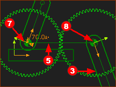
After Add Gear-Pair

PartRed-14-3 becomes a kinematically-defined Part ( its Part-Outline changes from Blue to Green)

PartRed-14-3 is the Geared-Rocker in the Kinematics-Tree.

The motion of PartRed-14-3 is defined by the motion of PartRed-14-1b and the gear-parameters that you define with the Gear-Pair dialog

The Pin-JointsRed-14-7Red-14-8 are the rotational-centers of the gears.

LineRed-14-5 joins the two gear centers and is called the Line-of-centers.

Notes

PartRed-14-2 may be stationary, or move relative to the Base-Part.

Lines can be CAD-Lines

Kinematics Trees: GEARED-ROCKER- before and after Add Gear-Pair

Kinematics-Tree BEFORE Add Gear-Pair

Kinematics-Tree
BEFORE Add Gear-Pair

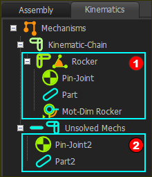
Kinematics-Tree before Add Gear-Pair

The Kinematic-Chain has two assemblies

Red-14-1b GST-Icon-KT-SolvedAlways Solved : Rocker

Any rotating-Part that is kinematically-defined before you do Add Gear-Pair.

It is important to know that this PartRed-14-1b may be moving or stationary, a Motion-Part, or  

Red-14-2 GST-KT-KinematicChain-Unsolved-icon-24 Unsolved

A Part that is NOT kinematically-defined before Add Gear-Pair.

A Pin-Joint.


Kinematics-Tree AFTER Add Gear-Pair

Kinematics-Tree
AFTER Add Gear-Pair

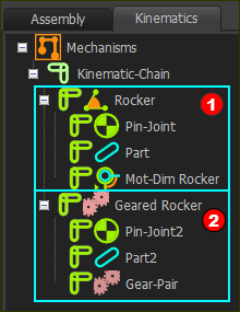
Kinematics-Tree after Add Gear-Pair

The Kinematic-Chain now has two Solved Kinematic-Sub-Assemblies:

Red-14-1b GST-Icon-KT-SolvedAlways Rocker - a kinematically-defined rotating-Part .

Any rotating-Part that is kinematically-defined before you do Add Gear-Pair.

Red-14-2 GST-Icon-KT-SolvedAlways Geared-Rocker - a kinematically defined rotating-Part.

Pin-Joint

Part

Gear-Pair element

The motion of a GEARED-ROCKER is a defined by the motion of RockerRed-14-1b and parameters defined in the Gear-Pair dialog.


Basic Gear-Pair Arrangements

Use Add Gear-Pair for different gear arrangements.

A)Two gears, with fixed centers

B)One gear orbits around a gear with a fixed center.

Use the same command for each gear arrangement.


Gear-Mesh: Videos Examples

We can use the Gear-Pair dialog to get these different gear-arrangements.

Gear-Pair: Fixed centers

Mesh: External

Mesh: Internal

Step Down:

# Teeth Gear 1 < Gear 2

Step Up:

# Teeth Gear 1 > Gear 2

Step Up:

# Teeth Gear 1 > Gear2

Step Down:

# Teeth Gear 1 < Gear2

gp-fixedstepdownex_zoom30

gp-fixedstepupex_zoom30

gp-fixedstepupint_zoom30

gp-fixedstepdownint_zoom30

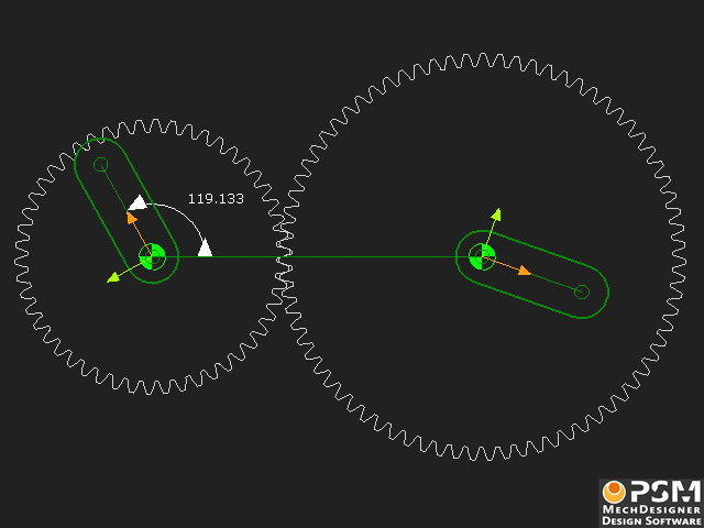
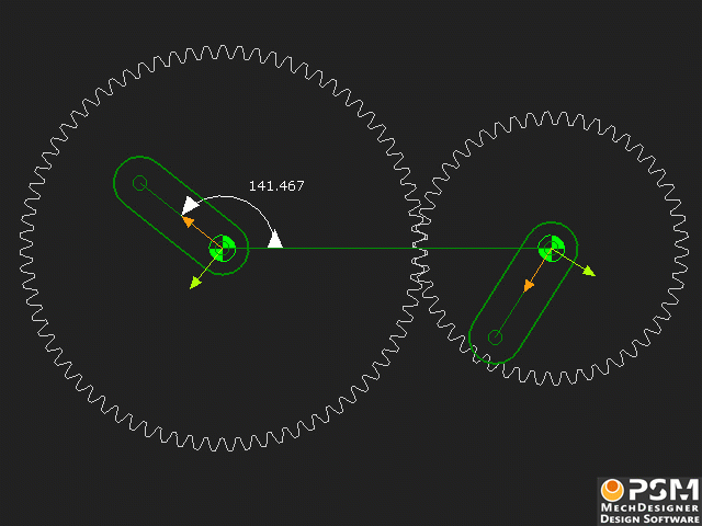
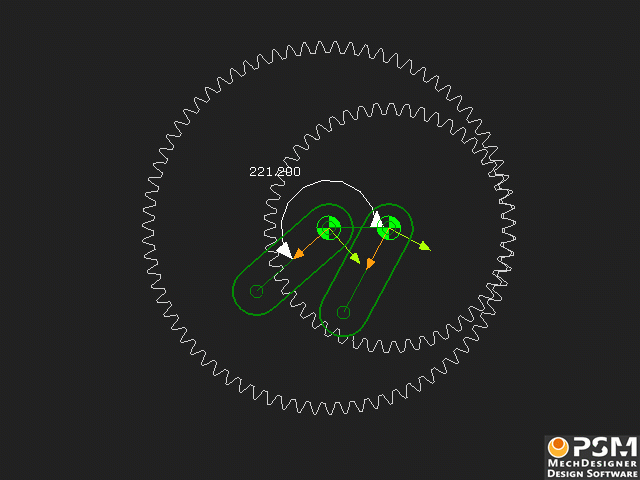
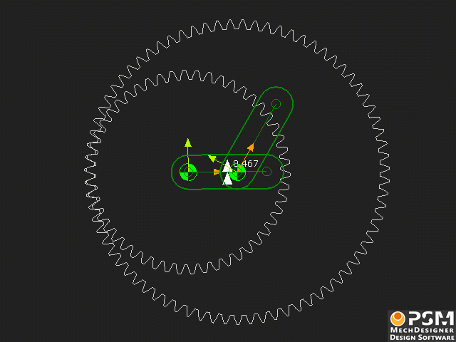
Click to play each video

Gear-Pairs: Orbiting centers

Mesh: External

Mesh: Internal

# Teeth: Gear 1 < Gear 2

# Teeth: Gear 1 > Gear 2

# Teeth: Gear 1 > Gear2

# Teeth: Gear 1 < Gear2

Fixed Gear is smaller and internal to Orbiting Gear