Preamble
Engineers can select Follower-Roller bearings in catalogs and on the web. To select a bearing, they must calculate the payload, estimate contamination, lubrication, operating temperature, and decide on the reliability they need. If the Follower-Roller bearing fails, then the difference between the actual and design environment can be reviewed. If necessary, the engineer can change the Follower-Roller bearing to one that has shields or seals to reduce contamination, or one that has a full compliment of rollers or balls.
It is rare that a Follower-Roller is faulty. All bearing suppliers have high standards for steel quality, manufacturing processes, and heat-treatment. The capacity of bearings from different suppliers are similar.
Cam-shafts have been used for many years in billions of vehicles. The cams are fully lubricated and wear is minimal for 10,000,000+ rotations.
However, each type of industrial packaging machines is often designed and then built maybe only 10 times, perhaps 100 times, and rarely 1000+ times.
It is easier to analyze the stresses in a cam than the stresses in the raceway and rolling elements in a bearing. However, it is left to the machine designer to choose the correct steel, manufacturing, heat-treatment process, and method of lubrication to give a cam the operational-life and reliability as demanded by their customers.
Nominal Contact Stress - Cylindrical Follower-Roller and Line Contact
As a cam rolls under Follower-Roller (or the Follower-Roller rolls over a cam) the cam and the Follower-Roller become stressed and slightly flattened. The stresses at and below the contact-surface are quite complex. They are not like the stresses that you can calculate from Tension, Bending or Torsion. Hertz was the first to calculate the stress field. The stress is now frequently termed Hertzian Contact Stress (Reference Hertz (1881) has done the hard work to derive the equations we need to calculate the stress when there is contact between two bodies that are conformal or non-conformal.
[H. R. Hertz, "Über die Berührung fester elastischer Körper (On Contact Between Elastic Bodies)" Journal für die reine und angewandte Mathematik 92, 1881 pp. 156-171].), Hertzian Stress, or Contact-Stress.
We calculate for you the Maximum Shear Stress from the contact-stresses immediately below the contact between the Cam and Follower-Roller.
It is convenient to consider two contact types:
Line-Contact : between two cylinders with parallel axes. Line-contact is equivalent to a cylindrical Follower-Roller in contact with a 2D-Cam. The contact is actually a narrow rectangle.
Elliptical-Contact : between bodies with more complex shapes. Each body has a radius in the rolling direction, and at least one body has a radius that is orthogonal to the rolling direction. Most frequently, elliptical-contact is made when a barrel shaped Follower-Roller is in contact with a 2D-Cam or a 3D-Cam.
Hertzian Stress at the Cam Surface (Line Contact)
 Contact Stress field |
|
||||||||||||||||||
2D-Cams and Cylindrical Follower-Rollers result in so called Line contact. •the Cam-Profile is prismatic, although each point along the Cam-Profile has a different radius-of-curvature. •the Follower-Roller is cylindrical, with a constant radius (obviously!). When the force between the Cam-Profile and Follower-Roller is very low, the contact is almost a thin line. As the force increases, the Cam-Profile and Follower-Roller deform and the contact becomes a narrow rectangle across the width of the Cam-Profile and Follower-Roller. The area of the rectangle is equal to the width of the Cam (L) × Contact-Width (2×b) - see 'b' in the image above. |
|||||||||||||||||||
|
|||||||||||||||||||
Parameters to calculate Hertzian Contact-Stress for Line-Contact.
Equivalent Radius-of-Curvature,
Equivalent Elastic Modulus,
Half-width, , in direction of rolling:
Mean Hertzian Stress:
Maximum Hertzian Stress:
Substituting for gives, Maximum Hertzian Stress:
|
|||||||||||||||||||
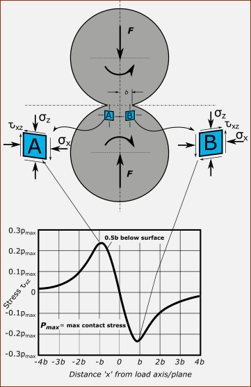
Stress below the center of the Line Contact axis (x=0)
 Principal Contact Stresses directly under the rolling axis of a Cylindircal Follower-Roller and 2D-Cam |
||
The image above shows the principal stresses (all compressive) relative to the Maximum Hertzian Contact Stress, , directly below the center-line of contact. Scale of Horizontal-Axis : Scale of Vertical-Axis : : Compressive Stress in the vertical direction : Compressive Stress in the horizontal direction, in direction of rolling : Compressive Stress in the horizontal direction, in direction that is across the width of contact : Tresca Shear-Stress, (also known as ). It is equal to the maximum difference between any two of the principal stresses. Maximum of Shear-Stress, (Line Contact)
Depth below surface of Maximum Shear-Stress, (Line-Contact)
|
Mohr's Circles for stress state at 0.78b below the Cam's Surface
Mohr's Circles are another way of representing the principal stresses, but at a slice beneath the surface. The slice is at the depth equal to the Maximum Shear-Stress () - at below the surface ( is half the contact-width) |
|
 |
|
Principal Stresses: , , This image shows the Mohr's Circles for the Principal Stresses, , , , at the depth of . Each compressive stress is relative to the Maximum Contact Stress, , which is at the surface, but at a depth below the surface. @0.78b = –0.3 @0.78b = –0.15 @0.78b = –0.75 Maximum Shear Stress, From the scale of the Mohr's Circles, we can see that the Maximum Shear Stress (vertical axis) is one half the diameter of the largest circle.
|
|
In many cases, surface roughness, friction, lubrication, thermal effects, and residual stresses will invalidate the exact results from Hertzian analysis. Consequently, you should regard the Hertzian Contact-Stress as guidelines that correlate with experimental tests that find allowable stress limits. |
|
Schematic of Orthogonal Shear Stress due to of 'Free Rolling' and 'Traction Rolling'
|
Orthogonal Shear Stress moving through the contact zone - image to left. The Hertzian Contact Stress contact-stresses lead to Octahedral shear-stress and Orthogonal shear-stresses under the surface at the contact. The image to the left schematically illustrates how a cylinder rolling over a flat body in the absence of friction develops subsurface stresses. The stress at a depth of 0.78b, just below the center of the contact, is the maximum shear stress. - see analysis above. It occurs at 45° to the contact surface. Orthogonal shear stresses are parallel and perpendicular to the contact surface and in-front of and behind the contact line/rectangle. The orthogonal stress in-front and behind have equal and opposite signs. The magnitudes of the orthogonal stresses are always lower than the magnitude of the shear stress. However, the range of the orthogonal stresses is higher than the shear stress and is thought (not by all) to be a more important contributor to the development of contact fatigue damage. The Orthogonal Shear Stress is believed to be significant with respect to sub-surface Fatigue Cracks. The maximum Orthogonal Shear Stresses are : • below the surface. • to in-front and behind contact axis. •, with a full range of . |
Shear Stress and Traction with Rolling Friction Many elements that are in contact will slide as they pass over each other. For example, gear-teeth, and flat-faced followers sliding along a cam. There is always a coefficient of friction and thus a friction force. This results in tangential, normal, and shear stresses that superimpose on the Hertzian Contact Stresses, described above. These stresses are illustrated schematically in the image.  Schematic of stress that superimpose with a rolling cylinder with traction or friction |