Follower Roller : Contact Force Analysis
Before you can analyze Contact-Force and Contact-Stress between the Cam-Profile and Follower-Profile, you must configure the model so that the power flows to and from the Cam |
Background
Contact-stresses that are between the inner race, outer race, and balls or rollers limit the life of a bearing. However, the contact-stresses are extremely difficult and complex to calculate. Luckily, suppliers of Follower-Roller bearings have done the hard work for engineers. They publish the capacity that limits the life of Follower-Roller bearings with units of force rather than units of stress. The load, as a force, is much easier to calculate. However, the capacity of a Follower-Roller is also strongly influenced by lubrication, contamination, temperature, and the reliability you need. To include these, we use the capacity modification factors in the ISO 281-2007 standard. |
Follower-Roller Bearings and Load Ratings
Follower-Roller bearings have three load ratings: •Basic Static Load Rating, •Basic Dynamic Load Rating, •Fatigue Load Rating, |
Note 1: Rating, Capacity, and Load-Limit are equivalent terms.
Note 2: The ratings have units of Force. However, the actual limit is the maximum allowable contact-stress between the inner-ring, rollers, and outer-ring, and not the contact-stress between the Cam-Profile and Follower-Roller. We consider the contact between the Cam-Profile and Follower-Roller in the next topic, when we review the capacity and life of the Cam.
Static Load Rating, Co, (Units: N)
The balls or needles/rollers deform the inner working surfaces of a Follower-Roller bearing by approximately 1×10⁻⁴ (0.0001) of its mean diameter when the load is greater than the Static-Load-Rating, . The load may leave visible marks (Brinell marks) on the bearing's raceways. Amazingly, the marks do not have a measurable effect on the life of the Follower Roller bearing, if you significantly reduce the load at other times. The Static Load Rating is important when the Follower: •rotates very slowly (n < 10RPM) •has a slow oscillating movement or •receives a short duration load Short duration loads may occur at start-up, emergency-stops, machine jams, or when the active process has a short duration, such as a cutting action. Of course, unintended machine breakages may lead to a short duration load. Static-Load Safety Factor,
|
Basic Dynamic Load Rating, C, (Units: N)
Typical statement in a bearing catalog: The Dynamic Load Rating, , is that radial load (for a radial bearing) of constant magnitude and direction at which a sufficiently large number of apparently identical bearings can endure for a life of one million revolutions. The Life of a bearing has a probability. An life indicates 10% of the bearings statistically fail within one-million rotations, while 90% survive. The Dynamic Load Rating assumes the load and speed are constant. If the load or speed, or both, are not constant then we must calculate an equivalent load and speed. When we consider a typical application of a Follower-Roller bearing loaded against a rotating cam: •Nearly always, the load continually changes - See Payload Signatures •Nearly always, because the radius of the cam continually changes, the speed of the Follower-Roller continually changes. |
Bearing Life - Variable Speed and Variable Load, () (without Modification Factors)
|
|
Life, in millions of rotations (-) |
|
Basic Dynamic Load Rating (N) |
|
|
Equivalent Bearing Load (N) |
|
|
- ball bearing (-) |
|
|
- roller or needle bearing (-) |
Equivalent Load, ()
|
|
|
Equivalent Follower-Roller Load (N) |
|
Time interval, as a percentage of the total time period |
|
Rotation Speed of the Follower in the interval (RPM) |
|
Follower Bearing Contact Load in the interval (N) |
|
Roller Bearings = 10/3 Ball Bearings = 3 |
Bearing Life: Hours (), years, ()
|
|
Life - hours |
|
Life - years |
|
|
Rotational speed of the Follower-Roller () |
|
|
Ball bearing (-) |
|
|
Roller or needle bearing (-) |
Bearing Life: Hours, Alternative Formulation ()
|
|
Life, in millions of rotations (-) |
|
Rotational speed of the Follower-Roller () |
|
|
Life-Factor |
|
|
Speed-Factor |
Bearing Life Modification Factors
We can adjust the Dynamic Rating Life, , with two parameters. They compensate for the reality that a bearing does not operate under ideal conditions. The ISO 281 standard provides the details of how to calculate these parameters. |
||
|
|
Reliability Modification Factor for reliabilities other than 90% |
|
Integrated Life Modification Factor, which accounts for lubrication, contamination., and the fatigue load rating |
|
|
Basic Life Rating - see above. |
|
Reliability Factor:
 Reliability against bearing life. |
Bearing damage and fatigue failure have a pseudo-random character. Thus, even bearings that seem identical - the same batch of steel, identical geometrical characteristics, identical operating conditions (load, speed, lubrication, etc.) - will fail after different operating times. Thus, the life of a bearing is a statistical evaluation of a large number of bearings. The chart to the left indicates the percentage of bearings that fail as a function of rotations. The scale of the x-axis is multiples of 1×million rotations, or Statistically, after •1 × L10 rotations: ~10% of bearings fail (90% do not fail) •5 × L10 rotations : ~70% of bearings fail (30% do not fail) •8 × L10 rotations : ~90% of bearings fail (10% do not fail)
|
|||||||||||||||||||||||||||||
Reliability Chart Table.
|
||||||||||||||||||||||||||||||
The Weibull distribution function is commonly used to predict the life of a population of bearings at any given reliability level. The equation for the life adjustment factor, , for reliability is:
|
||||||||||||||||||||||||||||||
Life Modification Factor:
|
||
|
- |
a function of ( )... |
|
- |
Fatigue Limit (N) |
|
- |
Contamination Factor |
|
- |
Viscosity Ratio |
|
N |
Equivalent Load |
Fatigue load limit,
ISO 281 defines the fatigue limit, , for a bearing as the load below which metal fatigue does not occur. With poor lubrication, or contamination of the lubricant in particular, the bearing can fatigue at loads which are significantly below the fatigue limit,. For the fatigue limit to be a valid value, the lubricant film must fully separate the rolling elements from the raceways and that dents from contaminants or from handling do not exist on the rolling surfaces. The contamination factor, takes into account how the level of solid particle contamination of the lubricant influences the calculated bearing fatigue life. The particles cause indentations in the rolling surfaces of the bearing, and these indentations increase the local contact stress, which reduces the expected fatigue life. • means perfectly clean conditions without any indentations. • means severely contaminated conditions resulting in pronounced indentations. In the SKF rating life model, contamination, designated by the contamination factor, , acts as a stress raiser, thereby reducing the fatigue load limit to . We then compare the reduced fatigue load limit, , to the actual bearing load, , to give a fatigue resistance value of •Clean conditions and a load that is less than the fatigue load limit results in a high fatigue resistance value. •Contaminated conditions and a load that is more than the fatigue load limit results in a low fatigue resistance value. The stress-raising influence of contamination on bearing fatigue depends on a number of parameters, including: bearing size, relative lubricant condition, size and distribution of solid contaminant particles and types of contaminants (soft, hard, etc.). Therefore, it is not meaningful to specify precise values for the contamination factor that would have general validity. If a catalog does not list the Fatigue Load Limit, and the mean bearing diameter is less than . (nearly all Follower-Roller Bearings are less than ), then you can use this approximation: |
|
|
Roller and needle bearings |
|
Ball bearings |
Mean Diameter = (Outside Diameter + Inside Diameter) / 2 |
|
Viscosity Ratio,
The Viscosity Ratio, , indicates the quality of the lubricant film. The lubricant-film separates the raceway and rolling-elements. It is expressed as:
Note 1: Viscosity Ratio, , assumes the “standard” surface finish of commercial Follower-Roller bearings. Note 2: An approximate relationship between Film Thickness Ratio, , and Viscosity Ratio, , is:
|
Reference Kinematic Viscosity,
The Reference Kinematic-Viscosity (sometimes called the Rated, or Required Viscosity) is: if |
|
if |
|
|
- inside diameter of Follower-Roller |
- outside diameter of Follower-Roller |
|
Kinematic Viscosity at operating temperature,
We calculate for you the Viscosity, , at the Operating Temperature, from the Viscosity at two other temperatures. Nearly always, the two temperatures are and , but not necessarily. The lubricant's data-sheet usually specifies the Viscosity at ( ) and ( ) You must enter all five parameters in the dialog: •2 x Temperature: and •2 x Viscosity: and , at temperatures and •Operating-Temperature: . We calculate the Viscosity at the Operating-Temperature, . |
Contamination factor:
If a contaminant particle moves to the inside of a bearing the rollers (or balls), outer-race, and inner-race are prone to dent because of the small internal bearing clearances and the small rolling radii of the rollers (or balls). An indent leads to localized stress, which will decrease the life of the bearing. The contamination may even prevent the rollers (or balls) rotating. The contamination factors that reduce the lifetime of a Follower-Roller bearing are a function of the: •diameter of the Follower-Roller •lubricant film thickness (viscosity ratio, ) •size, type, and hardness of the particle contaminant. Guide values for the contamination factor are in the table below. They are typical levels of contamination for well lubricated bearings. We find for you the contamination factors with these lubrication methods:
|
|||||||||||||||||||||||||
Circulating oil lubrication with On-Line Filtration, before being supplied to the bearings.
|
|||||||||||||||||||||||||
Oil bath Lubrication, or Recirculating Oil Lubrication, with Off-Line Filtration.
NOTE Research concludes that it is difficult to accurately find the oil cleanliness especially if you analyze very clean oils. It is easy to pollute an oil-sample, with oil additives that precipitate into the oil and particle calculation. |
|||||||||||||||||||||||||
Grease Lubrication, Contamination Factors
|
|||||||||||||||||||||||||
Simplified Values of Oil Contamination Factor ,
Contamination Level for Grease Lubrication
|
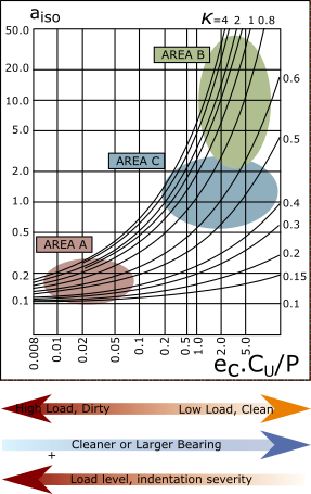
Life Modification Factor: - an interpretation (SKF catalog)
|
When the lubricant is contaminated with solid particles, permanent indentations in the raceway can be generated when these particles are rolled-over. At these indentations, local stress risers are generated, which will lead to reduced life of the rolling bearing. This life reduction due to contamination in the lubricant film is taken into account by the contamination factor . Guide values for the contamination factor can be taken from from the table above, which shows typical levels of contamination for well lubricated bearing. In the case of severe contamination (), failure may be caused by wear, and the life of the bearing can be far below a calculated modified rating life. |
Area A : very high load and/or severe indentations. The lubricating conditions in this domain can only marginally improve the expected fatigue life, so the potential improvement to the life depends on what dominates the relationship between the contamination level factor and the load level, . To achieve a greater rating life, either the load must be reduced, or the cleanliness must be improved, or both. |
|
Area B : high life modification factors, convert a low dynamic-rating life sufficiently to produce a large rating life. In this part of the graph, the life modification factor is sensitive to small deviations of the estimated load level, cleanliness factor and lubrication conditions. For example, mounting or transport damage can change the lubricating conditions, induce slightly higher loading with larger indentation severity, may result in a change from 50 to 5, or a 90% loss of rating life. In cases of a large life modification factor, but a low basic rating life , the impact of variations in operating conditions should be evaluated in a sensitivity analysis. |
|
Area C : the life modification factor is less sensitive to changes. Deviations from estimated load level, cleanliness factor and lubrication conditions (for example, from uncertainties in temperature) will not substantially affect the value of , which means the resulting rating life is more robust. In the load level domain, Area C has the ranges: for ball bearings for roller bearings |
EP-additives in the lubricant
ISO 281 states... ... at exceptionally low rotational speeds (dm x n <10000), the generated film may be less than adequate and unlikely to form elastohydrodynamic lubrication and unlikely to separate the rolling element and raceway contact. Then you must use EP-additives to improve life. In accordance with ISO 281, EP-additives can be taken into consideration in the following way: •For operating temperature lower than 80°C (175°F), EP/AW additives in the lubricant may extend bearing service life when and the factor for the contamination level and the resulting . Under those conditions, a value of can be applied, in place of the actual , in the calculation of for a maximum advantage of up to . •At a viscosity ratio and a contamination factor , a value κ= 1 can be used in calculation in the case of lubricants with EP-additives that have proven effective. Under severe contamination (contamination factor ), the effectiveness of the additives under these contamination conditions must be proven. The effectiveness of the EP-additives can be demonstrated in the actual application or on a rolling bearing test-rig. •EP/AW additives in the lubricant are used to improve the lubrication condition of the bearing in situations where small values are in use, e.g. when . Furthermore, EP/AW additives are also used to prevent smearing between lightly loaded rollers and raceway, for example, when especially heavy rollers enter a loaded zone at a reduced speed. Some modern EP/AW additives containing sulphur-phosphorus, which are most commonly used today, can reduce bearing life. Generally, SKF recommends testing chemical reactivity of EP/AW for operating temperatures above 80°C (175°F) |
When NOT to use the “Systems Approach” Life Modification Factor.
It does not apply to the following operating conditions: •Life exceeds 200 000 hours, it is indicated "over 200,000". •Very large load imposes to the bearing (More than C0 or more than 50% of C!!!. •Very light load imposed on the bearing (P<Co/60) •Very high speed. •Water ingress into lubricant. •Abnormalities such as wear, corrosion, or electric erosion. •Large misalignment between inner and outer rings. •Very large and hard foreign debris intrudes to (Life is shorter than the calculation result). •Viscosity when driving is 10% or less of necessary dynamic viscosity. |
Variable Speed and Variable Load - with Life Adjustment Factor
The Dynamic Bearing Life equation assumes that the bearing's speed and load do not change! There are equations you can use to compensate for a variable speed, a variable load, and for when both the speed and load are variable.
Of course, the speed and load against a Follower-Roller continuously vary when it is rolling around a cam of varying radius. We calculate an equivalent bearing load, .
|
||
where: |
||
|
|
Equivalent Follower-Roller Load |
|
|
Duration of interval, , as a percentage of the total operating period
|
|
|
Rotation Speed for interval |
|
|
Bearing load for interval |
|
- |
Life exponent - Roller Bearings = 10/3 Life exponent - Ball Bearings = 3 |
|
- |
Life adjustment factor for interval |
Oscillating Follower-Roller
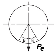
When the outer race of the Follower-Roller bearing does not make a complete rotation, but oscillates back and forth, a lower equivalent radial load can be calculated using the formula below: |
|
|
where: - equivalent dynamic radial load - actual oscillating radial load - angle of oscillation, in degrees - Roller Bearings - Ball Bearings |
|
|
Active Follower-Roller rotations
Active Follower-Roller rotations are those when the payload between the Cam-Profile and the Follower-Roller is positive. The number of active rotations is dependent on the type of Cam. •Conjugate Cam: active rotations of one Follower-Roller are when the acceleration is 'positive' during the Rise of the Follower, and 'negative' acceleration during its 'return', and opposite for the other Follower-Roller. •Groove Cam: active rotations are throughout the complete machine cycle. However, the roller must reverse its direction after it changes cam-flanks. It is not loaded as the Follower-Roller traverses backlash between cam-flanks. •Forced Closed Cam: active rotations are throughout the machine cycle. |
System Life
Conjugate cams, or Parallel Indexers, have two or more Follower-Rollers, and often your machine has many cams. All of the Follower-Rollers in a machine are then considered to be a 'system'. For machine design reliability purposes, it is important to know the system life of your machine. The evaluation combines the L10 lives of all the bearings so that you can answer the question, 'How long will the machine perform with 90% reliability?' In simpler terms, the system L10 reliability will be less than the lowest individual L10 rating life. The following formula is used to calculate the 'System Rating Life' of the Follower-Roller. |
|
|
where: - rating life for the system of bearings - rating life for the individual bearings in the system - Roller Bearing - Ball Roller |