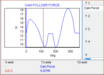
Contact-Force and Contact-Stress Analysis
Why do we compare the Contact-Force to the load capacity of a Follower-Roller, and compare the Contact-Stress to the load capacity of the Cam-Profile?
The fatigue life of an component is a function of the stress that is imposed on the component.
However, to calculate the stress imposed on the Follower-Roller elements is very difficult. Luckily, suppliers have done the hard analysis, and estimated the capacity of a Follower-Roller as a Force rather than stress.
To calculate the stress imposed on a Cam is relatively straight-forward, as we know the contact-force, the material properties, and the geometry. We, as engineers, must estimate the life of the cam from the stress.
Follower: Payload Signature
 Typical Load Signature of a Follower-Roller |
Payload Signature of the Follower-Roller A Follower-Roller usually rotates a non-integer number of times as the cam rotates one time. Over time, the Payload Signature of the Balls or Needle-Rollers against the inner-ring and outer-ring of a bearing becomes the statistical-average or equivalent load. •Payload: Pseudo-continuous speed and pseudo-continuous load. Similar to a normal bearing. •Loaded Elements: Similar to a normal bearing. The depth/width of the outer-ring of a Follower-Roller bearing is deeper/wider to limit its distortion. •Geometric Properties: The dimensions of a Follower-Roller bearing are constant. •Material-Properties: Commercial Follower-Roller bearings are optimized for life. Thus, we use the Basic Static Load Rating, Basic Dynamic Load Rating, and Fatigue Limiting Load to calculate the life of a Follower-Roller bearing. |
Cam Profile: Payload Signature
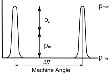
 CAM-STRESS: Mean-Stress = (Max+Min)/2; Stress Amplitude = (Max-Min)/2; Max Stress = 2*Mean, Minimum Stress = 0 MPa |
Each point along the surface of the Cam-Profile (and just below) is stressed one time as the roller moves across it each machine cycle. The stress that each point along the cam experiences is zero at all other machine angles. The stress is said to be pulsatile (like heart-beat pulses) with a pulse period of 2.π or 360º. Cam: •Payload: pulsatile, each point on the cam is loaded once per cam rotation. •Loaded Element: the cam •Material : Decided by design engineer, material supplier quality control, heat treatment •Geometric Properties: Radius continuously changing, Surface-Finish decided by engineer. Thus, we compare the working contact-stress with the permissible contact-stress of the cam material, its quality and its heat-treatment. |