Follower-Roller Design Arrangements
When the Follower-Profile is circular, we use the term Follower-Roller.
The Follower-Part, or Follower, is the part in the cam-system that supports the Follower-Roller.
Follower-Rollers
Generally, there are two types of Follower-Roller bearings:
•Stud
•Track
See SKF cut-away views of Stud and Track type Follower Rollers
Both the Stud and Track types have many variants to suit different applications and working environments - for example: axial or non-axial guidance; sealed for life or oil lubricated; protected with shields, seals or left open; corrosion resistant or not; ball, roller or needles; full-compliment of rolling elements or in a cage; cylindrical, barrel (crown) shaped, or logarithmic (proprietary).
Stud Follower-Roller
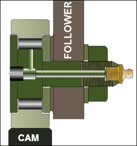 Stud Follower. The Stud is also the inner-race to the bearing. |
Stud Follower-Rollers Most typically: •the stud is an extension of the inner-ring •thick-walled outer-ring •one or two rows of rollers or balls •shields, seals, or neither •optional eccentric sleeve to enable fine adjustments. The Cam is typically 2-3 mm wider than the Follower-Roller to prevent 'edge' stresses. |
Track Follower-Roller
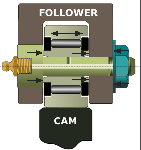 Preferred Yoke Mounting of Track Follower |
Track Follower-Rollers A Yoke (clevis, or fork) and Pin supports the Follower-Roller. In the image - the important detail is: •When the nut tightens (on the right), the shoulder of the support bolt (on the left) moves to the right against the inner-ring. It forces the inner-ring against the right, inside face of the yoke. Thus, the yoke does not deflect inwards when the nut is tight. The outer-ring of the Follower-Roller should not touch the inside face of the yoke. The outer-ring can float axially, without restriction, by approximately 0.2mm. |
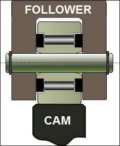 Acceptable Yoke Mounting of Track Follower |
•It is possible to use two circlips (snap-rings) to locate the support pin. •The inner-ring can move to the left or right and against the inside faces of the yoke. •The outer-ring floats to the left or right, up against the flange-rings of the track bearing. •The outer-ring should not touch the inside face of the yoke..
|
Stud Follower-Rollers and Form-Closed Cams
Groove, or Track, Cams
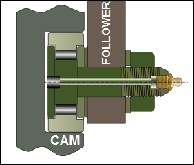 DESIGN 1: Typical Follower, with Stud, in a Cam-track. |
DESIGN 1: One Follower-Roller bearing To allow the Follower-Roller to rotate, the width of the cam-groove is greater than the diameter of the Follower-Roller bearing. Thus, the design has two disadvantages: 1.Backlash The clearance between the Follower-Roller and the Cam-Flanks, like any other backlash in the system, will cause impact forces (knocking) when the backlash is traversed. 2.Wear When the Follower-Roller traverses the backlash, the Follower-Roller must rotate in the opposite direction, which it cannot do instantly. Thus, it skids (slides) until it rolls along the Cam-Flank again. The skidding action wears the surfaces of the Follower-Roller and the Cam-Flank. |
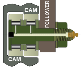 DESIGN 2A: Two, EQUAL diameter Stud Followers. The 'deeper' cam-track must be undercut. |
DESIGN 2: Two Follower-Roller bearing There are two Follower-Roller on the same stud / shaft. These designs aim to: 1. Reduce Backlash With good manufacturing tolerances, the backlash can be reduced. 2.Reduce Wear The Follower-Rollers do not need to change their rotational directions, and thus they do not scuff/wear as much as those Follower-Rollers that do need to change their rotational directions (see DESIGN 1)
DESIGN 2A: Two Follower-Roller - Equal Radius See image 'DESIGN 2A'. When the Follower-Roller diameters are equal, each roller must have a clearance between it and the non-working flank. There are four surfaces to machine: two working/active surfaces for the Follower-Roller to roll against, and two non-working/clearance surfaces to make sure the Follower-Roller do make contact.
DESIGN 2B: Two Follower-Rollers - Different Radius See image 'DESIGN 2B' The Cam-Flanks do not need to be undercut. It is easier to manufacture. Note: When the load is small and/or the , and the elimination of backlash is important, one roller can be steel and the other rubber. The rubber roller can be loaded against one cam flank to act as a spring to force the rigid roller against the other cam-flank and so act as a pre-load. The pre-load force might be quite low. Example: a camera lens. |
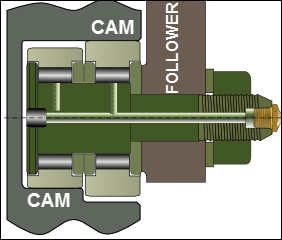 DESIGN 2B: Two, DIAMETER diameter Stud Follower. The deeper cam-track does not need to be undercut |
Conjugate-Cams
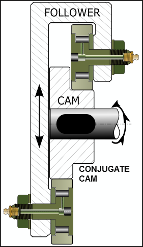 DESIGN 1: Typical Follower, with Stud, in a Cam-track. |
Conjugate Cams These have two Follower-Rollers, which are not on the same shaft/stud. Each Follower-Roller is at a different position in the Follower. Advantages: •The diameter of the Follower-Roller bearing can be different to suit the particular loading cycle. For example, the upper roller may support the weight loading and other forces, while the lower roller does not. •With accurate machining, backlash can be eliminated, •Care must be taken to make sure the bearings do not crush the cam at any point if any clearance becomes an interference as you rotate the cam. The mechanical-advantage to crush the cam is huge.
|