Force-Closed and Form-Closed Cam Types
Your design must make sure the Cam-Profile and Follower-Profile are in contact.
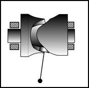
You have two design options: Force-Closed Cam or Form Closed Cam.
This topic shows the schematics of cam types with a Follower-Roller and not Flat-Faced Follower.
Follower-Rollers are far more common as there are many standard sizes and types of roller bearings intended for Cam Systems.
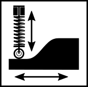
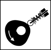
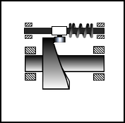
Force-Closed Cams
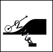
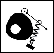
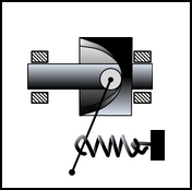
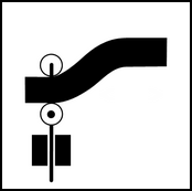
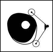
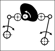
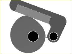
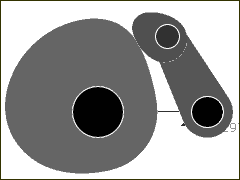
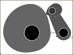
An external force makes sure the Follower-Roller is in contact with the Cam-Profile.
These examples use a Spring as the external force.
Other external forces are: Gravity (slow speed), Air, and Hydraulic-Cylinders.
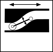
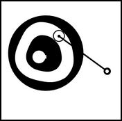
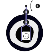
RECIPROCATING FOLLOWERS (also called Translating Follower)
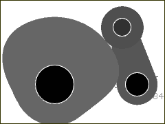
Oscillating Follower (also called Swinging-Arm Follower)
Force-Closed Cams: Advantages and Disadvantages Advantages: •Only one Cam-Profile to manufacture •Less manufacturing precision •Less expensive to manufacture •Zero backlash (play) - when the Follower-Profile does not lift off the cam! •Reduced Scuffing (with Follower-Roller): The surface-speed of the Cam-Profile and the Follower-Roller will be equal to each other at low speeds, which reduces or eliminates scuffing-wear on the cam-profile. At high speeds, or where the radius of the cam varies rapidly, there may be some scuffing (mismatching velocities) as the Follower-Roller cannot accelerate or decelerate quickly enough. In the case of a machine jam, you can: •Configure the mechanism so that the radius of the cam decreases as the mechanism moves towards where it is most likely to jam. Say, as the tool moves into the assembly-area, the Follower-Profile will lift off the Cam-Profile. •Alternatively, it is possible to use an air-cylinder to actively lift the Follower in response to a sensor detecting a jam in the machine. Disadvantages: •Cam-Lift: You must calculate the Spring's (or Cylinder's) parameters (Free-Length and Spring-Rate) to make sure the Follower-Profile does not lift off the Cam-Profile at all operating speeds. •Cam-Force: A Spring exerts a greater force on the Cam than a Form Closed Cam, which may reduce the operating life of the Cam-Profile and Follower-Profile. •Machine Frame Stiffness: A Spring and the Follower-Part exerts a greater force on the machine-frame. •Residual Energy after Stop/E-stop: At stand-still, the Spring exerts a torque on the cam when the pressure-angle is not zero, which tends to turn the cam. •Cam-Shaft Speed Fluctuation:The Spring Force tends to increase the torque fluctuation on the cam-shaft as the Spring changes its length.. The torque fluctuation is greater if the pressure-angle is high. The speed of the cam-shaft may fluctuate: the spring resists the Cam-Shaft rotation during the 'rise', and assists its rotation during the 'return' segment (or vise versa, if arranged in the opposite sense). If the speed fluctuation is excessive (>10%) - the machine may damage itself - see Torque, Overrun, and Power. |
||||||||||||||||||||||||||||||||
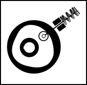
Form-Closed Cams (Body-Closed Cams)
An Internal Force makes sure Follower-Profiles remains in contact with Cam-Profiles.
There are three design types.
|
|||||||||||||||||||||||||||||||||||||||||||||||||||||||||||||||||||||||||||||||||||||||||||||||||||||||||||||||||||||
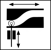
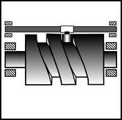
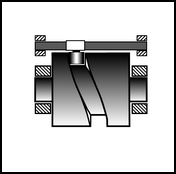
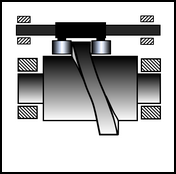
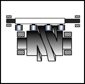
A Follower-Roller is in a Cam-Groove (also called a Cam-Track). The two side walls of the groove are the Cam-Flanks. It is the most common design of Form-Closed Cam. Its disadvantage is that there must be Backlash between the Follower-Roller and the Cam-Flanks. Reciprocating and Oscillating Followers - 2D Cams
Reciprocating and Oscillating Follower - 3D Cams
Groove Cams: Advantages and Disadvantages Advantages: •It is the easiest Form-Closed Cam to design and manufacture. •There is one set-up for the machine tool. •It is not as sensitive to manufacturing accuracy as the Conjugate Cam Type. •A slightly oversized machine cutter will give a small clearance between the Follower-Roller and Cam-Profile. Disadvantages: •There must be backlash - even if small - between the Follower-Roller and Cam-Profile. •If there is a machine crash, then the machine must stop to prevent more damage, unless there is a Torque Limiter in the Output Transmission.. •As the follower starts to decelerate, the Follower-Roller will move from one cam flank to the other. There are three damaging consequences when the Follower-Roller moves from one Cam-Flank to the other: oScuffing: The Follower-Roller must change its rolling direction. The Follower-Roller and the cam-profile will scuff, until the Follower-Roller begins to roll again. A Follower-Roller with a large diameter skids more than a smaller Follower-Roller - it has a larger friction moment, but its inertia increases as the square of its radius. oImpact Dynamics: There is impact between the Follower-Roller and Cam-Profile, which gives a 'shock' load to the Follower, output-transmission components and payload. The impact can significantly increase the contact-force and other forces in the machine components of the output-transmission. oOver-run: The input-transmission and motor may overrun while the torque-load is zero as the backlash is traversed. There is a tendency to overrun even without backlash, as the torque-load reduces to zero when the acceleration reaches the 'crossover' point. Backlash makes overrun worse, sometimes significantly, if the Motion-Law has a rapid torque reversal - for example the Modified Trapezoid Motion-Law. |
||||||||||||||||||||||||||||||||
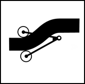
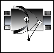
 2: Two Follower-Rollers (also called Conjugate Cams)
There are usually two Follower-Rollers on the Follower-Part, that act on two Cam-Profiles. The motion of the two Follower-Rollers is identical. Reciprocating Follower - Translating Follower
Oscillating Follower - Rotating Follower
Conjugate Cams: Advantages and Disadvantages Advantages: When the Follower-Rollers (most common) are pre-loaded against the cam-flanks, the backlash can be removed and they roll. This means: •Impact does not occur at the cam-flank when backlash is crossed when, or shortly after, acceleration becomes negative after positive, and vice versa - the crossover •Scuffing wear is eliminated after acceleration crossover from positive to negative, or vice versa, as the roller bearing starts to roll again. Disadvantages: •More expensive to manufacture as the machining of the Cam-Profiles and operating machine itself need greater precision. •Usually, the Follower-Rollers will not lift off the cam in the event of a machine jam. Damage may occur to other machine components until the machine can stop. It is possible to design the Follower-Rollers such that one of them lifts off the cam in the event of a machine jam. |
||||||||||||||||||||||||||||||||||||||||||||||||||||||||
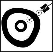
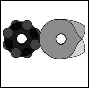
 3: More than 2 Follower-Rollers in one Follower-Part - Indexing Cams
Indexing: A motion that repeats and progresses in one direction. The motion 'index-period' followed by a 'dwell-period', to give an intermittent, or progressive, motion. Indexing cam assemblies nearly always have rotary input and output shafts. The output-shaft has several Follower-Rollers that are equally spaced around a turret or star. The Follower-Rollers engage with the cam in sequence. Follower-Rollers replaces each other at the end of each index cycle. Each Follower-Rollers rotates to its original position after a number of motion cycles. Commercial Indexers are pre-assembled, precision cam-boxes. The cam and the Follower-Rollers are inside the cam-box and not visible to the end-user. The input and output shafts are available, outside the cam-box, to connect to the drive-motor, gearing and machine with stiff couplings. Indexing Types:
Indexing Terminology:
|
||||||||||||||||||||||||||
Follower-Profile Shapes
In this topic we use the term Follower-Profile for the element that should remain in continuous contact with the Cam-Profile. Follower-Profiles are nearly always circular - and given the name Follower-Roller - and they usually roll. However, Follower-Profile have a number of different shapes, each with advantages and disadvantages. The Follower-Profile is a child to the Follower-Part, which is more usually termed Follower. Typical Follower-Profile Shapes for Rotating-Followers
|
