Over-run and Power
In this topic, we review:
•the harmful effects of Over-run.
•the Motor Power you need to drive a cam system.
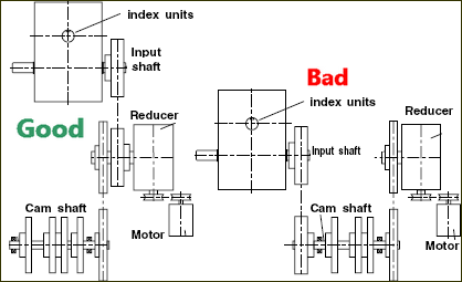
One important aspect of input-torque (see here) is: •a period of negative torque, where the Load drives the Motor •a rapid change from positive to negative torque, particularly for some cam-laws (motion-laws). These have an influence on the design of the input-transmission. If the input-transmission is excessively elastic and/or it has a significant amount of backlash, an over-run effect takes place. What is over-run? •During the positive torque phase, the payload resists the cam and the cam-shaft winds-up (it twists) - the elasticity of the input- transmission winds-up and its backlash is taken up. •As the torque reduces, the cam-shaft unwinds, until the torque is zero. Then the system goes free while the backlash is moves across the “other-way”. •The transmission winds-down in the opposite direction, the payload system over-runs its drive. The output from the Follower leads the input to the cam-shaft •When the payload is no longer driven by the motor, or even the payload starts to drive the motor, the speed of the motor can rapidly increase. This increase in the speed of the motor is called OVER-RUN. The amount the speed increases can be considerable, even in well designed machines. •If the overrun happens very quickly, there is also a significant cam-shaft acceleration. The importance of the cam-shaft acceleration cannot be overstated.
In terms of everyday language:
Notes: 1.The second term is usually zero, because the acceleration of the input-shaft should be zero, as the input-shaft should rotate with a constant angular velocity. During overrun, however, the input cam-shaft accelerates. Therefore the second term is not zero. 2.The first term will increase in proportion to the square of the increase in the angular velocity of the input-shaft. Therefore the Actual Output Acceleration increases drastically. The inertia loading (proportional to the output acceleration), can increase due to the increase in shaft angular velocity and angular acceleration by as much as , in bad cases. How to reduce Over-Run?
Kinetic Energy, Flywheels, Speed Fluctuation If we ignore any input braking effect and friction loading, there is a constant amount of Kinetic-Energy in the cam-system when a cam mechanism is running. Some of the Kinetic-Energy is transferred from the input to the output as the output inertia accelerates, and from output to the input when the output inertia decelerates. The loss of energy from the input causes the input to slow down, and then when the input regains energy, it speeds up again. The Output Kinetic-Energy varies from zero, when the load is in its dwell-period, to a maximum, when the load is at its maximum speed. With an input-transmission that is efficient in the forward and reverse torque conditions, the Input Kinetic-Energy must fluctuate by the same amount. We can find how much inertia at the input is required to limit the speed fluctuation of the input to 10%. - a 10% speed fluctuation limit is a arbitrary - you may specify any limitation.
Equating these two expressions gives:
and similarly
Example 1 - Input Transmission Design Improvement |
||||||
|
||||||
Example 2 - Input Transmission Design Improvement
|
||||||


Power
The power being transmitted at any moment at any point in the transmission is its instantaneous load multiplied by the instantaneous velocity:
where: - torque at the cam - angular velocity at the cam For most applications, the input velocity is virtually constant, and is usually expressed as the number of cam-shaft revolutions per minute. The peak power is thus:
Input Velocity =
where:
We can now give an expression for the Peak Power of a cam system in terms of the cam-shaft speed and the input torque, with input torque being a function of the output loading, the input and output stroke and the input torque coefficient of the motion-law as described:
This is the Peak Power, in the system used by the cam. To find the size of a motor to drive the mechanism, we must add any power losses in the input transmission (friction, gearing etc). But we can take advantage of the fact that there is usually a significant amount of kinetic-energy associated with the cam-shaft. The power fluctuates during the motion period. But the power to drive the cam is very low during a dwell period. The reserve of energy, derived from the input inertia, supplies the extra power needed to cope with the peak requirement, provided that the input inertia is adequate, as described above. It is therefore necessary only to have a power source that can provide the 'average power' of the motion cycle. The average power is never more than half of the peak power, and if the dwell period(s) are much longer than the motion period(s), the input energy reserve can be restored during one cycle with a power input much less than half the maximum. Where the power source is an A.C induction motor, quite apart from the benefit of a fairly high armature inertia (at high speed), there is the advantage that its peak torque is more than twice its normal torque rating. Thus, it is always safe to select a motor with a:
This would be for one mechanism. Clearly, you must calculate the power needed for all of the mechanisms in the machine. |