Load Types, Normalized Load Types, and Input Torques
This topic reviews:
•Payload and Load Types
•How to normalize Payload Types with coefficients:
•The effect on input-torque for different Payload Types, and how we can normalize it as the coefficient,
Terminology:
Payload and Load or equal terms.
Capacity is the ability of the mechanism to perform the duty for a specified lifetime.
 Payload: Load Types
It is important to know the different types of payload when we design a cam-mechanism. The different loads are referred back to the Cam-Shaft. |
|
|
A: Force or Torque: constant. For example, friction, gravity, work loads. |
|
B: Force or Torque: proportional to displacement. For example, a spring. |
|
C : Force or Torque: proportional to velocity. For example, viscosity. |
|
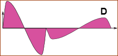
D : Force or Torque: proportional to acceleration. For example, inertia. |
|
E : Force or Torque: conforms to a special function. For example, an engine cycle. |
EXAMPLE 1A: Gravity, Spring, and Inertia: Speed Dependence |
|
 MECHANISM AT 'LOW-SPEED' |
The two images show the same payload-types on a cam mechanism, at two different speeds. The payload-types in the example are: • Constant Load • Spring Load • Inertia Load You can see that at high-speed the payload at At high-speed, the load also becomes negative at |
 SAME MECHANISM AT 'HIGH-SPEED' |
|
EXAMPLE 1B : Gravity, Spring and Inertia: Different Pre-load of SpringThe image below shows the period of negative loading when the cam has a 'falling' motion. In such a case, the Follower-Roller would lose contact with the Cam-Profile, and you would lose control of the payload. To make sure the Follower-Roller remains in contact with the Cam-Profile: •Improve the motion design to reduce the maximum negative acceleration. •Use an enclosed track, a blade cam, or a conjugate cam - or - •Increase the Pre-Load(A) and/or Spring-Rate(B) |
|
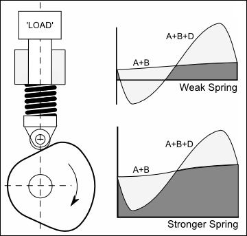 Payload between Roller and Cam when Load is moving down. |
|
Most indexing mechanisms, and many reciprocating and oscillating mechanisms, have a load that combines a Constant Load (A) and an Acceleration Load (D), with less significant amounts from the other load-types. Constant Load - friction forces (e.g. bearing seals), gravitational force, and other work loads - can be resolved into a single force or torque resisting the output motion. Acceleration Load - from the inertia of various masses - can be resolved into a single equivalent inertia connected to the Follower. Total load = inertia load + constant load. The peak of the total load usually is at the same point as the maximum inertia load. Other common Payload Types •Index mechanisms: Friction(A) + Inertia(D). •Spring-loaded reciprocating mechanisms: Friction(A) + Spring Pre-Load(A) + Spring-Rate(B) + Inertia(D). •Very high-speed mechanism: possibly significant Viscous Load (C) + Inertia Load(D). The maximum value and proportion of each type of load component (A, B, C, D and E) depends on the application. Thus, there is an infinite number of load patterns. It is possible to tabulate normalized values for the most common combinations. Payload for Conjugate Cams The idealized design of Conjugate Cams eliminates the need for a Spring to maintain the contact of the Follower-Roller against the Cam-Profile. Frequently, the Follower-Roller rollers are adjusted, or designed, to give an 'optimal' pre-load against the Cam-Profile, so that the Follower-Rollers do not slip. This is an idealized design. More frequently, manufacturing and machining tolerances, mean it is difficult to guarantee contact between throughout the cam's rotation. The Follower-Roller will often lose contact during some part of the machine cycle. Frequently, Conjugate Cams use a spring, air-cylinder or hydraulic device, to force one of the Follower-Rollers against the cam to eliminate backlash. The loading device only needs a short travel to compensate for manufacturing tolerances. |
|
 Normalized Loads
Inertia Load The maximum inertia load ( from these simple equations, of course : The Inertia Load or are nominal, and must be modified by the application of the Torsion-Factor, |
|||
and
|
|
- Output Stroke (Angular Displacement) |
|
|
- Output Stroke (Linear Displacement) |
||
|
- Acceleration Coefficient |
||
|
- Inertia Force at the Follower |
||
|
- Inertia Torque at the Follower |
||
|
- Equivalent Inertia referred to the Follower |
||
|
- Equivalent payload mass at the Follower) |
||
|
- Motion Period |
||
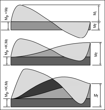
Friction Load A Constant Load, such as friction, is: • for linear motion • for rotary motion Referred to the mechanism output in both cases. Add the Friction Load to the Inertia Load. Spring Load When there is a load component that is proportional to displacement, such as a spring force, it is convenient to add the Maximum Spring Force to the Friction-Force, , or Friction-Moment, , as if it is a constant load. In that case, the total output-load calculation is conservative. These are safe values for preliminary designs. Load Mix: Inertia; Friction; Spring As an alternative to the conservative loading, we can take all three load patterns into account. When appropriate, the maximum load can be adjusted downwards by a load-mix coefficient, . Thus:
|
|||
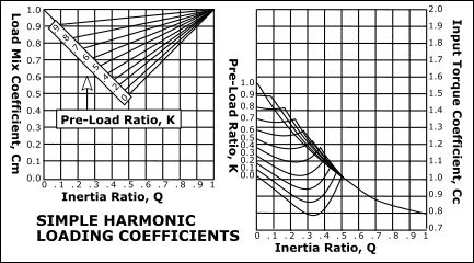
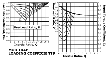
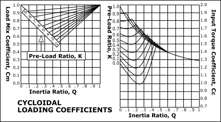
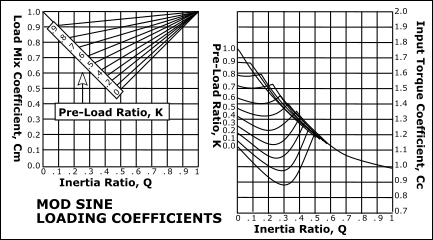
 Pre-load Coefficient (K); Inertia Ratio (Q).
Pre-load Coefficient, K
Inertia Ratio, Q
|
 Input Torque Coefficient
The input-torque (drive torque) varies throughout the motion. The variation is a function of the output-load and the motion-law. Since the output-load varies with the mix of inertia-load, spring-load, and constant-load, so too does the input-torque. For all cases, the mix is defined with the factors and , as defined above. For each motion-law, the instantaneous input-torque can be expressed as a function of the instantaneous output-load: |
||
|
for linear motion |
|
|
for rotary motion |
|
Where: : |
|
- cam output torque |
|
- output force |
|
|
- normalized velocity factor of cam-law |
|
|
- linear output stroke |
|
|
- angular input stroke |
|
|
- output torque |
|
|
- angular output stroke |
|
|
- efficiency of the cam and follower mechanism |
|
The instantaneous output load, or , is a function of the normalized motion-law factors, the load mix, and the payload. Thus, the above equations can also be expressed as: |
||
- or -
The maximum value of occurs during the acceleration phase. It can be simply expressed by introducing a normalized Input-Torque Coefficient, . Input Torque Coefficient (No Spring Loading, ) Thus: |
||
|
- for linear motion |
|
|
- for a rotary motion. |
|
|
- Peak Input Torque |
|
|
||
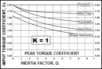
The value of , the Input-Torque Coefficient, can be evaluated for any motion-law and a range of load mix factors. The input torque patterns for some standard motion-laws are shown (below) for different values of and when (no spring loading). From these patterns it can be seen that there is a wide disparity between the input torques of different motion-laws, for all values of . |
||
Input Torque Coefficient, (K= 1, and Q= 0 – 1)
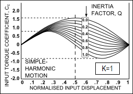 Simple Harmonic Motion |
Drive Torque Fluctuations with each Motion-Law. It is common to use the maximum value of the Input Torque Coefficient, , when the Inertia Ratio, Simple Harmonic Motion varies smoothly and gradually from a low positive peak to a moderate negative, which is a good characteristic. However, if this motion-law is preceded or followed by a dwell, there will be a discontinuity of acceleration at the start and end of the motion, and the dynamic response may be unacceptable. •When the Inertia Ratio is 1, the input torque of the Modified-Trapezoid varies rapidly from a high positive to a low negative value at cross-over (X=0.5): •A rapid reversal of Torque is bad because the input power source (motor) reaches a high drive torque which must change rapidly to high braking torque. This might cause severe overrun if the input transmission has low inertia. Over-run means the drive speed is greater than the nominal drive speed of the cam-shaft. •If the input has a low rigidity, the drive shaft will suddenly 'unwind' to reverse its direction of 'twist'. This can cause input speed-oscillation of the cam-shaft. •When the Inertia Ratio is 1, the input torque of the Cycloidal varies more gradually than the Mod-Trap motion-law , however, not as gradually as the Mod-Sine, and it also has a higher peak value than the Mod-Sine motion-law. •When the Inertia Ratio is 1, the input torque of the Mod-Sine varies gradually from positive to negative. •It varies more gradually than, and is better than, Cycloidal. This makes the Mod-Sine very tolerant of a bad input transmission which, combined with its good dynamic response properties, is the reason for its popularity. |
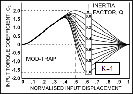 Mod-Trap |
|
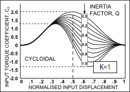 Cycloidal |
|
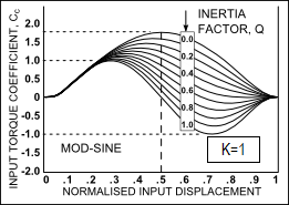 Mod-Sine |
|
|
This image shows the: Peak Values of Input-Torque Coefficient, against , Inertia Ratio, for each motion-law for constant loading (). |
Input Torque Coefficient, Cc (K= 0–1 & Q = 0–1)
The more complex loading pattern that includes a spring load component (0<K<1) we can find that both peak output load represented by and the peak input torque, represented by are considerably reduced with low pre-load ratios. |
 |
 |
 |
 |


