Cam Pressure Angle, ()
Pressure-Angle represents the efficiency with which a cam transfers the motion and force to the follower, and vice versa.
A Pressure-Angle is unavoidable.
However, a large value will increase the force contact-force between a Follower-Roller and a Cam-Profile, thus reducing the life of a Follower-Roller and Cam.
You want to push a door to open it ... : •If you walk to the door, and push the door-handle with a straight arm, with your arm at 90º to the door (perpendicular, (⊥), normal), you will open the door easily. You only need to overcome the inertia force of the door and any friction in its hinges. You will not need to hold on to the door-handle because the force is directly through your hand to your arm. •If you walk to the door, and push the door-handle with a straight-arm, but with your arm at an angle of 45º to the door, then : oyou need to overcome the inertia and friction in its hinges - equal to the force of the 90º example, above othere is also a force component that reacts against your hand to stop you hand sliding across the door. This force component is resisted by the door's hinges, which also pulls or pushes on the door-frame. The Total Force against your hand will increase. The angle with which your arm pushes against the door-handle is similar to the pressure-angle between a Cam-Profile and the Follower-Roller |
|||||
|
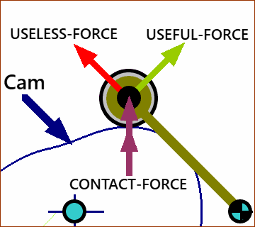
The three vectors of the force-triangle (usually taken at the center of the Follower-Roller) that result from the contact between the Cam-Profile and the Follower-Roller are the: •Contact Force : It is in the direction that is normal to the Cam-Profile at the contact-point between the Cam-Profile and Follower-Roller. •Useful-Force : It is in the direction in which the Follower-Roller must move. •Useless-Force : Its direction stretches a Rotating-Follower, or bends a Translating-Follower. From the three vectors, we can define the Pressure-Angle. The Pressure Angle, , is the angle ... ... from the direction in which the center-of the Follower-Roller must move ... ... to the direction of the contact-force, from the cam, acting through the center of the Follower-Roller. |
||||
Pressure Angle Limits: Rules-of-Thumb
To reduce the Maximum Pressure Angle
Force Vectors with different Pressure Angles |
|||||
 Pressure-Angle=30 degs |
Compare Contact, Useful, and Useless Force vectors. If the Useful Force of 100N, and: Pressure Angle = 30º
|
||||
 Pressure-Angle=45 degs |
Pressure Angle = 45º
|
||||
Overturning Moment
Overturning Moment applies to Flat-Faced Reciprocating Followers.
The Overturning Moment is the product of the Contact-Force and the distance from the contact-point to the sliding axis of the translating-follower.
We define the Re-Turning-Moment as the product of the reaction-forces that act on the linear-bearing and the distance between the linear-bearings (or the length of a linear-bearing)
|
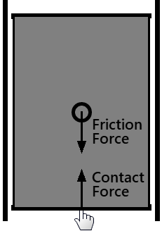
Understanding Overturning-Moment Imagine you want to slide a plank of wood along the floor, but between two walls. The plank is 2m long, 1m wide, and the 2m length is along the walls. There is a small gap. The Plank is uniform. However, it is cut so that it contacts the wall only at its ends, 2m apart. (against the floor) = Friction-Coefficient () × Mass × Gravity (). Note: do not confuse Friction-Coefficient, , and Pressure-Angle, ! If the friction force is constant, the Friction-Force vector is nominally through the Center-of-Mass and parallel to the wall - 0.5m from the wall. No Over-turning Motion If you slide the plank (slowly) with a hand that is in line with the center-of-mass, the plank will not tend to rotate. In the ideal case, the wall does not need to react against the sides of the plank. The wall does not, theoretically, need to be there. Although it would be difficult to do without the walls! |
|
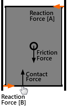
IMPORTANT: ignoring Friction against the wall. Overturning Moment Now, push the plank at a point nearer to one wall (so that the contact is offset from the center-of-mass and friction-force vector. Overturning Moment = Frictional force(Ff) × perpendicular distance to your hand from plank's center-of-mass 'axis'. Assuming the Friction-Force does not change, the further away from the plank's center-of-mass you push, the greater the over-turning moment. The overturning-moment will tend to rotate the plank. The wall prevents it rotating, of course. Re-turning Moment (to coin a term) The wall resists the plank at opposite corners of the plank (nominally) Re-turning moment = Reaction Forces from the walls × length of plank If you increase the length of the plank, the reaction-forces from the wall become less, but the returning-moment remains the same. Over-turning moment = Re-turning moment Over-turning moment = Contact-Force × distance to the 'sliding-axis' from the contact-point. Re-turning moment = Reaction-Force at one end of the Sliding-Joint × distance between reaction forces in Sliding-Joint. |
Example
|
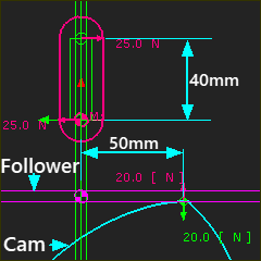
In the image: we can see the contact-force between a Cam-Profile and Flat-Faced Follower is 20N, and it is 50mm from the vertical sliding axis of the Translating-Follower. Thus: Overturning Moment = Contact Force (20 N) × Distance to Contact Point from Sliding-Axis (50 mm) = 1000 N.mm Overturning-Moment = Re-turning-Moment Re-turning Moment (1000 N.mm) = Distance between (or Length of) Sliding-Bearing(s) (40 mm) × Reaction Force (25 N) Notes: During a typical follower motion, the contact point continually moves across the flat-face from one side of the sliding-axis to the other. This analysis ignores any friction-force in the sliding-bearings and friction-force between the Cam-Profile and the Flat-faced-Follower. |
|
How to reduce the Over-turning Moment:
|
||