Curvature (κ) and Radius-of-Curvature (ρ)
Curvature ( κ ) of a curve is the degree to which it deviates from a straight line. Curvature is a property of the curve. Radius-of-Curvature ( ρ ) is the reciprocal of Curvature.
= Radius-of-Curvature = Curvature By definition, Curvature of a: •straight-Line is zero •circle is finite I find it easier to mentally translate Radius-of-Curvature as the Radius-of-the-Curve as that is what it is! The Radius-of-Curvature of a point on a Curve can be represented by the radius of the osculating-circle at that point. You can also think of the Radius-of-Curvature as the Radius of the Osculating Circle. The Radius-of-Curvature of a Cam-Profile continually changes. |
||
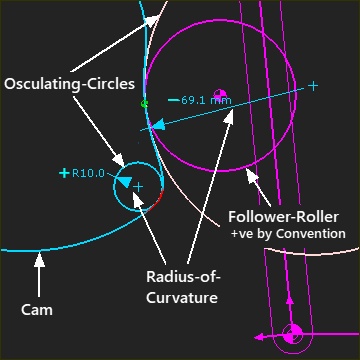 Osculating Circles (Inside and Outside of Cam) |
||
Radius-of-Curvature - sign convention 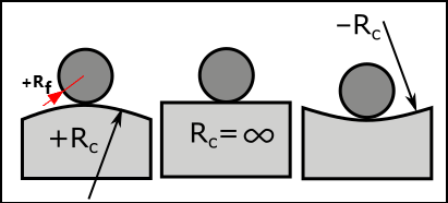 Radius of Curvature Convention for Planar Cams The Radius-of-Curvature changes its sign(±) when the osculating-circle moves from one side of a curve to the other side of a curve. Mathematically, the sign convention for the Radius-of-Curvature is arbitrary. However, the Radius-of-Curvature convention with Cams is: •The Radius of the Follower-Roller is positive* (+ ve) •If the Cam is Convex to the Follower-Roller, then the Cam's curvature is positive (+ ve) •If the Cam is Concave to the Follower-Roller, then the Cam's curvature is negative (– ve) Thus, it is possible, but not usually good-practice, for the positive Radius-of-Curvature of the Cam to be less than the positive radius of the Follower-Roller. If the Radius of Curvature that should be convex becomes less than 0mm, then Undercutting occurs. If the Radius of Curvature that should be concave becomes less than the Radius of the Roller, then the Roller can not physically contact the Cam-Profile. With a Groove-Cam, the Radius-of-Curvature of one Cam-Flank is positive and the other Cam-Flank is negative. * The Follower-Roller has a negative radius when the cam is inside the Follower-Roller! |
||
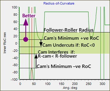 Graph of Radius of Curvature |
||
It is useful to consider the Radius-of-Curvature Ratio.
Radius-of-Curvature - Rule-of-Thumb
In MechDesigner, we use the Cam-Data FB to plot the Radius-of Curvature of the Inner and Outer Cam. In the plot above, the green indicates when the Radius-of-Curvature ratio = 1 In the plot above, the , which is very low, and much less than the Rule-of-Thumb of When the radius changes from +ve to –ve, or vice versa, the Ccm has an Inflection-Point. At the Inflection-Point the cam is flat and its radius-of-curvature is infinite (). The graph is vertical as the radius-of-curvature snaps from to , or vice versa. |
Radius-of-Curvature and Undercutting
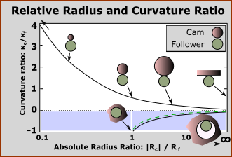 Curvature Ratio vs Absolute Radius Ratio |
If the Radius-of-Curvature of the cam is small, make these design checks: Contact Hertzian Stress : As the Radius-of-Curvature gets smaller, then for a given Load, the Contact-Stress between the cam and the Follower-Roller becomes larger.
(Line- Contact) Heat Treatment : Heat treatment is more likely to crack the steel if its Radius-of-Curvature is small. Flat-Faced Followers : When the follower is a Flat-Faced Follower, the Radius-of-Curvature of the cam must be +ve at all times. |
|
 Cam Undercutting |
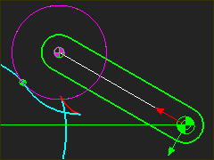
Undercutting In MechDesigner, you control the motion of the Follower. In your machine, the contact of the Follower-Profile with the Cam-Profile controls the motion of the Follower. Thus, if the Cam-Profile is undercut, the Follower cannot move with the motion as specified. In MechDesigner, you can scrutinize the model to look for a 'dove-tail' - see model to the left. Also, you can use •a Cam-Data FB and Graph FB, or •the 2D-Cam dialog > Display tab : Enable Show Radius-of-Curvature |
|
Crown / Barrel Rollers and Elliptical Contact
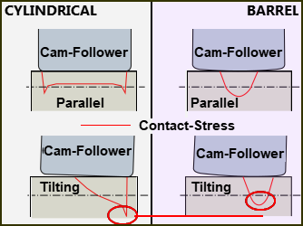 Schematic of Maximum Contact Stress of Cylindrical and Barrel Cam-Followers |
When to use a Cylindrical Follower-Roller or a Barrel Follower-Roller is a function of the type of machine and how well the follower and cam's rotational-axes can be aligned. Cylindrical Roller With perfectly parallel axes, the contact-shape between a Cylindrical Follower-Roller and a 2D-Cam is a rectangle - see the left and top example in the image However, if the rotational axes are not parallel, the Follower-Roller tilts and rolls along its edge - see the left and bottom example in the image to the left. The contact is distorted and the maximum Contact-Stress is significantly more than the nominal value for Line-contact. Barrel Rollers. The contact-shape of a Barrel-Roller and Cam-Profile is a small ellipse. If the rotational-axes are not parallel, the contact-shape moves across the Cam, but the Follower-Roller does not roll on its edge. The contact shape is not distorted. The maximum value of Contact-Stress is not more than the nominal value that is calculated for Elliptical-contact. |
The nominal maximum contact-stress of a barrel-roller is greater than that of a cylindrical-roller. However, if a cylindrical-roller tilts, its actual maximum contact-stress is greater than that of a crown-roller. The permissible tilt angle of a cylindrical-roller is very small, ( <0.1° ), and thus a barrel-roller is a good design option in many cases. Although, the tilt is not unlimited. of course See Tilt and Skew Limits of Cylindrical Follower-Rollers |
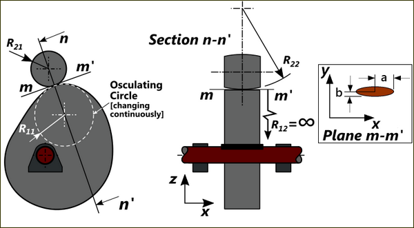 Radius of Curvature Convention for Cam and Barrel Rollers |