Build a Crank-Rocker
Summary of this Step
1.Add two(2) more Parts and three(3) more Joints to the model that you completed in Tutorial 1 2.Explain the concept of a dyad, and the R-R-R dyad in particular 3.Review the kinematic elements in the Kinematics-Tree 4.Explain why a dyad does not change the Mobility of a kinematic-chain. |
Terminology
Term : |
Definition |
|---|---|
Motion-Part : |
A Part whose motion you control with a Motion-Dimension FB. |
Rocker : |
The name in the Kinematics-Tree for a Motion-Part that rotates. |
Crank: |
Generic term for a Rocker whose motion is uniform angular velocity. |
Dyad : |
An assembly of two Parts and three Joints. |
R-R-R dyad : |
A dyad with three Pin-Joints - this is one of the five dyads that we can construct on a Plane. |
Dyad Closure : |
A different way to assemble (construct) the two Parts in a dyad. |
Four-bar : |
A kinematic-chain with one Motion-Part (typically a Crank) and one dyad (typically an R-R-R dyad). |
kinematically-defined : |
A Part or kinematic-chain whose Mobility=0. The Parts are solved. |
Video of Tutorial 2A: STEP 2.1

Video: Build a 4-bar Mechanism
Add the Parts and Pin-Joints
Note: Add Parts that are approximately equal in length to the Parts that are in the images.
|
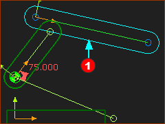
STEP 1: Add a Part
The new Part is in the graphics-area. Degrees-of-Freedom: Each Part has three degrees-of-freedom. |
||||||||||||||
|
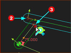
STEP 2: Add a Pin-Joint
The Points move to together at the new Pin-Joint Degrees-of-Freedom: Each Pin-Joint removes two degrees-of-freedom from the Part. The new Part now has one degree-of-freedom. STEP 3: Do STEP 1 and STEP 2 again
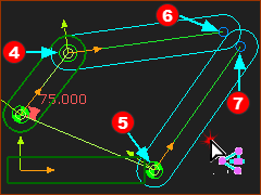
The Points move to together at the new Pin-Joint Degrees-of-Freedom: The two new Parts have a total of two degrees-of-freedom. |
||||||||||||||
|
|||||||||||||||
|
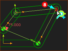
STEP 4: Add a Pin-Joint
The Points move to together at the new Pin-Joint Degrees-of-Freedom: The Pin-Joint removes two degrees-of-freedom. The two new Parts have zero degrees-of-freedom. The Mobility =0. The kinematic-chain is kinematically-defined, and solved. Perfect. Save your model - CTRL+S. |
||||||||||||||
You can see that the Part-Outlines are Green (or a type of green). This color indicates to you that the Parts are kinematically-defined and solved. You MUST make sure all of the Parts in the model are kinematically-defined before you analyze the motions and forces that act on Parts. Key Information:
The two new Parts may not assemble in the same way as the image above. See Step 2.1A to reconfigure the Closure of the Dyad. |
|||||||||||||||
Dyad - Kinematics-Tree
Explore the Kinematics-Tree:
|
||||
 Kinematic-Chain |
Explore the Kinematic-Chain
You can see the Rocker and the R-R-R dyad. Elements in the Rocker - the Motion-Part.
Elements in the R-R-R dyad:
Question: Why is it an R-R-R dyad and not a P-P-P dyad (Pin-Joints) Answer: The standard kinematic-term for Pin-Joint is Revolute-Joint. Therefore, it is R-R-R dyad. |
|||
 Rocker in the Kinematic-Tree |
||||
 R-R-R dyad in the Kinematic-Tree |
||||
|
||||
Notes: Crank vs Rocker
Unfortunately, it is easy to confuse the terms Crank and Rocker. Generic (engineering) terms: •Crank: a Part that rotates continuously •Rocker: a Part that oscillates back and forth Kinematics-Tree terms in MechDesigner: •A Rocker is a Motion-Part that can rotate continuously, or oscillate back and forth, indexes progressively, ... |