Scotch-Yoke: the R-P-P dyad
In this step, you will change the kinematic-chain to a Scotch-Yoke.
I do not know where the name Scotch-Yoke has come from. Do you?
However, it is a kinematic-chain that is frequently used in packaging, assembly, and textile machines.
You will add a Slide-Joint. The Slide-Joint is not along the CAD-Line that is from the start-Point to the end-Point of all a Parts you add to the model.
In this step, we dd a new Line to the Part, and then use it for the Slide-Joint.
See http://youtu.be/MrvAKlePm3k?t=33s
To assemble simple, four-bar kinematic-chains. We need: •One Motion-Part : A Motion-Dimension FB controls the motion of a Motion-Part. A Motion-Part is a Rocker or a Slider. •One dyad : All dyads have: oTwo Parts oThree Joints |
What is a Scotch-Yoke?
Below, there are two schematic images of a Scotch-Yoke. |
||
|
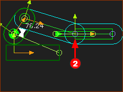
The Motion-Part is a: •Crank – colored Black. A dyad uses: •Three Joints: a horizontal Slide-Joint, a vertical Slide-Joint, a Pin-Joint •Two Parts: one horizontal sliding-Part – colored Red – and the other Part is... where? |
|
In the image above, where is the second Part in the dyad? The second Part of the dyad does not seem to exist. |
||
|
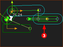
The other Part in the dyad is now in the image to the left. It is a: •Vertical sliding-Part – the Part is a sliding-block - colored Green. The kinematic-chains in the images to the left are kinematically equal, but they are slightly different physical designs of a scotch-yoke. |
|
|
||


Video:

Change the Kinematic-chain from a Slider-Crank to a Scotch-Yoke
The Scotch-Yoke looks like the images above. |
||||
|
STEP 1: Delete the Motion-Dimension FB
The color of the Part-Outlines in the kinematic-chain now indicate the Parts are NOT kinematically-defined. STEP 2: Edit the Base-Part
You are in the Mechanism-Editor again. STEP 3: Add a Motion-Dimension FB to the Pin-Joint The input to a Scotch-Yoke is usually a Crank (Rocker that rotates with a uniform angular velocity).
In the Kinematics-Tree, there is a Rocker and R-R-P dyad. We need an R-P-P dyad - one Pin-Joint and two Slide-Joints. |
|||
|
||||
|
||||
|
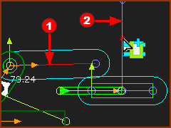
We will change the middle joint from an R joint ( Pin-Joint) to a P joint (Slide-Joint). STEP 4: Delete the Pin-Joint between the horizontal Sliding-Part and the long Part
|
|||
|
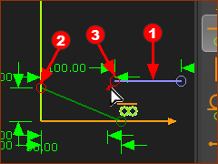
Note: I have moved the Blue Parts slightly. Refer to the schematic of the Scotch-Yoke at the top of this topic. The Block slides vertically in a slot that is in the Part that slides horizontally along the Base-Part (the machine-frame). Thus, we need a vertical Line in the Sliding-Part STEP 5: Add a vertical line to the Sliding-Part.
You are in the Mechanism-Editor again. |
|||
|
||||
|
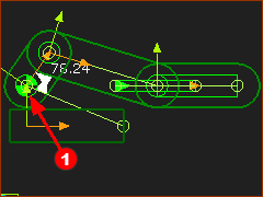
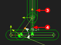
STEP 6: Add the Slide-Joint between the two Parts to complete the dyad.
|
|||
|
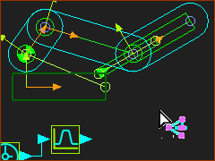
STEP 7: Cycle the Kinematic-chain
|
|||
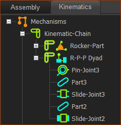
The Kinematics Tree for a Scotch-Yoke
|
The Rocker has three elements:
The R-P-P dyad has five elements, as do all dyads.
|