Assemble a Whitworth Quick Return
You are about to design a Whitworth Quick-Return Mechanism.
Why not start a new mechanism on a new Plane?
See also this link: http://youtu.be/MrvAKlePm3k?t=11s
A Whitworth Quick Return Mechanism has:
•One Motion-Part
•Two dyads
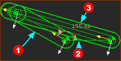
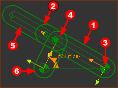
Whitworth : Motion-Part (Crank), Dyad 1, and Dyad 2
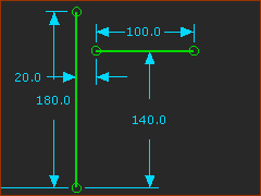
Motion-Part
|
Motion-Part
The vertical line anticipates that the output of the Whitworth mechanism is a sliding-Part. |
|
|
|
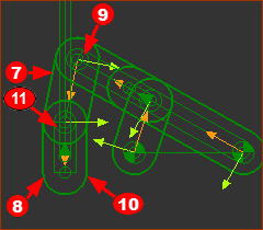
Dyad 1
|
Dyad 1
Dyad 1 R-P-R - is now complete. In this configuration of the Whitworth mechanisms, the input Crank rotates with a uniform constant velocity, and the output oscillates. Can you see what will happen if the length of the Crank is greater than the distance between the two Pin-Joints? See Change Closure of a dyad if the dyad is not in a closure you want. Use the Change-Dyad-Closure tool until the dyad is in the closure you want. |
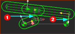
Dyad 2
|
Dyad 2
Dyad 2 R-R-P - is now complete. Note: If when you cycle the model (ALT+C), the Parts break somewhere in the machine-cycle, you will need to move the Lines in the Base-Part, or edit the length of Parts. See Change Closure of a dyad if the dyad is not in a closure you want. Use the Change-Dyad-Closure tool until the dyad is in the closure you want. |
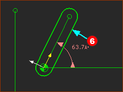
Other Configurations with the R-P-R dyad - Dyad 1.
|
The Crank In this case, each time the Crank rotates 360º the long Part How much the angular-velocity of the long Part |
|
The Slide-Joint is offset from: •End of the Crank by the length of the Line •Fixed Pin-Joint by the length of the Line When the configuration of the Slide-Joint is offset from the Pin-joints, the R-P-R dyad also has four Dyad-Closures - experiment. |