Elements in the graphics-area
In the graphics-area, different symbols represent different elements.
Edit the size of symbols with Application Settings > Accessibility tab > Graphics > Symbol Display Size Edit the color of symbols with Application Settings > Graphics tab > Display Colors > ... element types |
Element Symbols
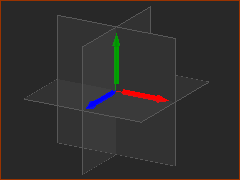 |
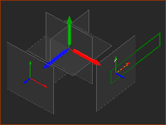
Planes and Axes in the Model-Editor workspace. There are three, fixed Planes in the Model-Editor. Triad: Red(X-axis), Green(Y-axis) and Blue(Z-axis) The axes intersect at the Global Origin of the model. They use the Right-Hand-Rule. Planes and Axes in the Mechanism-Editors workspace: Note: to see Planes in Mechanism-Editors: Show Solids in Mechanisms The smaller Red(x), Green(y) and Blue(z) axes are a Plane's axes. The origin of the green, rectangular Part-Outline, which is the Base-Part (see below), is coincident with axes of the active Mechanism-Editor and Plane. They use the Right-Hand-Rule. |
 |
|
 |
Part-Outlines Part-Outline : the term for the symbol of a Part you add to the model. • • The Base-Part is the frame of the active Mechanism-Editor. |
 |
Part-Outlines: solved and not-solved Parts A Part is solved or not-solved. To analyze the kinematics of a Part, you must make sure it is solved, when the Part's mobility is zero. •A Part that is solved has a Mobility of zero. The Part-Outline changes color - usually a type of Green •A Part that is not-solved has a Mobility greater than zero . The Part-Outline is usually a type of Blue * Green and Blue are the colors in this Theme. See also Application-Settings > Graphics tab > Display Colors |
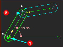 |
Pin-Joints in the Mechanism-Editor A Pin-Joint is a joint between Points in two different Parts. There are two symbols for a Pin-Joint:
|
|
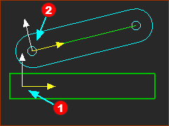
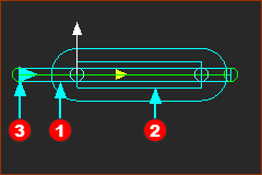
Slide-Joint in the Mechanism-Editor A Slide-Joint is a joint between two Lines - or one Line in two different Parts. The symbol for a Slide-Joint is:
|
 |
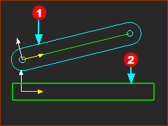
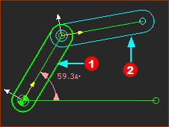
Part-Axes in the Mechanism-Editor The Part-Axes in a Mechanism-Editor are small •The Axes of the Base-Part •The Axes of Parts The CAD-Line and +X-axis are between the start-Point and end-Point of a Part. |
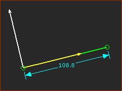 |
Part Axes in the Part-Editor The Part-Axes in the Part-Editor are large •The X-axis is collinear with the CAD-Line •The Y-axis is at +90º on the Mechanism-Plane The length of the CAD-Line maybe longer or shorter than the X-axis. |
 Mechanism-Editor  Part-Editor |
Sketch-Element and Point Symbols In a Mechanism-Editor, the color of Point symbols are the same as the Part-Outline to which they are a child. In a Part-Editor, the color of Point symbols are dependent on if they are Fully-Defined or Not Fully-Defined. |
 |
Point Symbols + : center-Point of an Arc or Circle +-- : center-Point that is merged with a start-point or end-Point
O-- : start-point or end-point of a Line or Arc
See Point Properties dialog. |
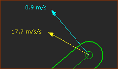 |
Kinematic Vector Symbols Enable Show Velocity Vector and/or Show Acceleration Vector in the Point Properties dialog. Each vector arrow shows the direction and magnitude. See Feedback Area > Vector Scale buttons. |
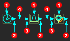 |
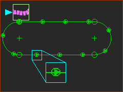
Function-Block, output-connector, input-connector, and wire Symbols
|
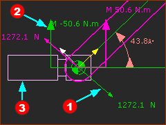 |
Force Vectors, Torque Vectors, Motor Symbol , the Motor-Symbol is the Power-Source.
See also Configure Power Source |
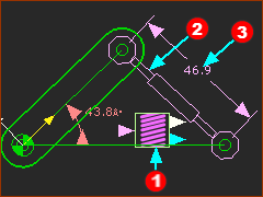 |
Spring Symbols The Spring FB element has three symbols in the graphics-area:
|
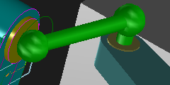 |
Ball-Joint and Connecting-Part Symbols •The Ball-Joint has its own symbol. •Edit its radius in the Ball-Joint dialog. •The Connecting-Part symbol replaces the Part-Outline when you join a Part to a different Part with two Ball-Joints. |
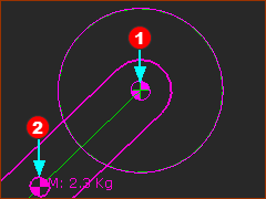 |
Mass Symbols
Total Mass on EACH Part = Mass of CAD-solids + MD-solids + User Defined Mass Properties |
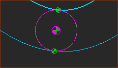 |
2D-Cam Contact Points When you add a 2D-Cam, you will see the contact points between the Cam-Profile and the Follower-Profile. |
 |
Motion-Points A Motion-Point is a small triangle inside a small circle. The circle is slightly smaller than the symbol for a Point. |
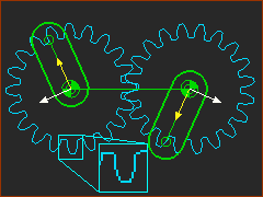 |
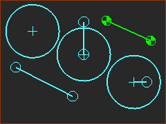
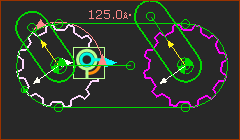
Gear-Pairs A Gear-Pair is two involute Gears. |
 |
Pulleys A Driving-Pulley is a different color to a Driven Pulley See Application Settings > Graphics > Graphic colors. |
Why is the Base-Part not Green?
 The Base-Part is not Green! |
If the Base-Part is not Green (or a similar color) when you add your first Mechanism-Editor, it is usual that Force-Vectors: Display is enabled.
To make the Base-Part Green, you should disable Force Vectors: Display
The Base-Part should be Green. |
Why is half of the Base-Part hidden by a Plane?
 BasePart partial hidden by a Plane. |
The Base-Part is partly hidden by a Plane if the:
When you enable Show Solids in Mechanism, we also show Planes. To hide Planes, do:
AND / OR
|
Why is the Base-Part not Green?
 The Base-Part is not green.  The Part-Outline of the Base-Part is in a different Mechansim-Editor. |
You can see Kinematic and sketch-elements of other Mechanism-Editors when these are enabled:
AND Enable Mechanism name-tab light-bulb in the other Mechanism-Editor (see Right-click Mechanism name-tab)
To hide the Part-Outline of the Base-Part in a different Mechanism-Editor, click the icon to disable the Disable Global-Setting.
|