Follower-Rollers: Design Specifications
Commercial Follower-Rollers are optimized for rolling along a Cam-Profile, or a Cam-Track.
It is helpful to understand their design features.
Compare a Housed Bearing and a Follower-Roller Bearing.
 Contact Stress/Pressure of Bearing in Housing |
Housed Bearings : The outer-ring is in a bearing housing and supported around its circumference within a bearing housing. •Most usually, the outer-ring is fixed in a housing and the inner-ring rotates with a shaft. •The contact between the outer ring and its housing is 'conformal' and with a small interference fit to make sure the bearing ring does not rotate in the housing. The load is distributed around the outer housing. •Thus, the outer-ring does not distort when a force is applied, since it is supported by the housing (unless the housing distorts). << The image to the left shows the bearing supported in a housing. The load around the outside of the bearing is a function of the fit between the housing and the bearing - the pre-load. |
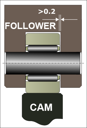
 Contact Stress of Bearing against Cam |
Follower-Roller Bearings : The outer-ring is not housed and is not supported around its circumference. •The outer-ring rotates and the inner-ring is fixed. •The contact between the outer-ring and the Cam-Profile is a line (or a very small patch) across the width of the Cam-Profile and Follower-Roller. The Hertzian contact stress is relatively high. •There is a tendency for the outer-ring to distort when a force is applied. To reduce distortion, the cross-section of the outer-ring is deeper than that of a normal bearing. <<< The image to the left shows a Follower-Roller against a Cam-Profile. The red spots indicate symbolically the contact-stress. |
Maximum Follower-Roller Angular Acceleration
|
The outer-ring of the Follower-Roller does not rotate at constant angular velocity. Nominally, the outer-ring's : •Minimum angular velocity is when it is in contact with the cam's Base-Circle •Maximum angular velocity is when it is in contact with the cam's maximum radius (its 'nose' in the case of the sketch to the left). The Follower-Profile must accelerate and decelerate as the radius of the cam changes. However, the maximum possible angular acceleration of the Follower-Roller is a function of its friction, radius, and inertia. The friction-force is not constant because the contact-force is not constant, and lubrication is not steady. |
|||||||||
|
||||||||||

Maximum Follower-Roller Rotational Speed
 Nominally, the maximum Angular Velocity of the Cam-Follower Bearing is at the maximum radius of the Cam |
Maximum Rotational Speed (RPM). The maximum possible speed of a bearing is a function of its design and how it is lubricated. Its maximum speed is usually given in the catalog. Alternatively, you can use this table (below) and this simple equation: Table Parameter(see below) = Stud or mean diameter(d) × Max Speed(RPM) E.g.: The maximum rotational speed of a Follower-Roller bearing; with an internal diameter ( stud diameter) of 10mm; Grease Lubrication: Oil Lubrication: |
||||||||||||||||||||
|
|||||||||||||||||||||
Minimum Load
Reasons to apply pre-load to a bearing are: enhanced stiffness, reduced noise, improved shaft guidance, extended bearing life, improved running accuracy, prevent skidding of the internal needles, rollers, or balls relative to the inner and outer rings. The minimum radial Follower-Roller load is approximately:
|
Skew and Tilt
![SKEW [view of Roller above Track]](gdi-cam-follower-housing--misalignment-skew.png "SKEW [view of Roller above Track]") SKEW ![TILT [sectional view of Roller and Track]](gdi-cam-follower-housing--misalignment-tilting.png "TILT [sectional view of Roller and Track]") TILT |
SKEW Rollers that skew increase the axial load and axial slippage between the Cam-Profile and Follower-Roller. The Follower-Roller skew angle specification is typically: •Skew Angle < 1.4 x 10⁻⁴ (°) or < 2.5 x 10⁻³ m.rad. TILT The maximum tilt capability of a: •Cylindrical Roller (typical) < 0.1°(1.7m.rad). •Barrel Roller (typical) < 0.25° (4.4m.rad)
|
Barrel Follower-Roller The outside surface of a Barrel Follower-Rollers is not cylindrical. They have a surface that has a radius They are intended to be used when the rotational axis of the Follower-Roller cannot be guaranteed to be parallel to the rotational axis of the cam. Barrel Follower-Rollers are also called Crowned Follower-Rollers, or even Spherical Follower-Rollers. Others have a surface described as Logarithmic Follower-Rollers - their actual profiles are commercially sensitive. |
|
 Schematic of Maximum Contact Stress of Cylindrical and Barrel Cam-Followers |
A Cylindrical Follower or a Barrel Follower? Whether to use a Cylindrical-Follower-Roller or a Barrel Follower-Roller is a function of the type of machine and how well you can align the Follower-Roller and Cam-Shaft rotational-axes. Cylindrical Roller - miss-alignment When the rotational axis of a Cylindrical-Follower-Roller is not parallel to the rotational-axis of a Cam-Shaft, the Follower-Roller will tilt relative the cam's axis, A Cylindrical Follower-Roller that tilts, will roll along its edge - see the bottom and left example in the image to the left. The contact is distorted. The maximum value of Contact-Stress is significantly greater than the nominal value that is calculated for 'line-contact'. Barrel Rollers. If the rotational-axis of the Follower-Roller is not parallel to that of the cam, the Follower-Roller will tilt relative to the cam's surface. In this case, the contact moves across the cam surface, but when the tilt-angle is within limits, it does not roll along its edge. The contact is not distorted much. The maximum value of Contact-Stress is not more than the nominal value that is calculated for elliptical-contact. |
Nominal Maximum Contact-Stress The nominal maximum contact-stress of a barrel Follower-Roller is greater than that of a cylindrical Follower-Roller. However, when a Follower-Roller tilts the actual maximum contact-stress of a cylindrical Follower-Roller is much greater than that of a crown Follower-Roller. The permissible tilt angle of a cylindrical Follower-Roller is very small, ( <0.1° ), and thus a barrel Follower-Roller is a good design option in many cases. The contact-stresses a Barrel Follower-Roller and a Cylindrical Follower-Roller experiences are different. If the Follower-Roller does-not tilt then the: •maximum contact stress of a cylindrical Follower-Roller is less (marginally) than that of a barrel Follower-Roller. If the Follower-Roller does tilt then the: •maximum contact-stress of a cylindrical Follower-Roller is more than the that of a barrel Follower-Roller. Thus, if you cannot guarantee alignment of the Follower-Roller alignment, you would use a Barrel Follower-Roller. |
|
Materials and Size Tolerances.
Outside Diameter Tolerance of Bearing Nominal outside diameter of a cylindrical Follower-Roller Bearing is: ~h5 , nominally zero to a small under-size. Nominal outside diameter of a crowned Follower-Roller Bearing is: 0.00 to –0.050mm , nominally zero to a under-size. |
|||||||||||||||||||||||||||||||||||||||||||||||||||||||
 Typical Yoke Cam-Follower Design |
INNER-RING: YES Surface Finish Maximum roughness should be Ra =1.6μm Diameter Tolerance There is a tolerance for the hole in the follower arm and also the diameter of the shaft through the inner-ring. JS6 (J7) : Hole through follower arm k5, g6, h6 : Stud through inner-ring, if heavy load, then k6. Form Tolerances Variation of Mean Shaft Diameter = 0.5 × Diameter Tolerance Variation from Circular Form = 0.5 × Diameter Tolerance |
||||||||||||||||||||||||||||||||||||||||||||||||||||||
|
INNER-RING: NO When space is limited, it is possible to use a Follower-Roller that does not have an inner-ring. The bearing's needle-rollers are in direct contact with the pin/shaft. Thus, the pin/shaft should have a specification that closely replicates the inner-ring of the bearing. Material: Through-Hardening steel : ISO 683-17 : 100Cr6 Case hardening steel : ISO 683-17 : 17MnCr5, 18CrNiMo7-6; or EN 10084 : 16MnCr5. Flame and induction hardening steel : DIN EN ISO 683-17 : C56E2, 43CrMo4, or DIN 17212 : Cf53. Hardness: •670HV +150 HV or: •58 to 64 HRC (Rockwell Hardness Scale 'C') If the hardness of the pin/shaft is less than 58HRC, the load-capacity of the Follower-Roller is reduced. This table shows how dynamic and static load capacities become reduced as the shaft's hardness is reduced. |
||||||||||||||||||||||||||||||||||||||||||||||||||||||
|
|||||||||||||||||||||||||||||||||||||||||||||||||||||||
INNER-RING: NO... continued Minimum Case Hardening Depth at which hardness is still greater than 550 HV, HRC 52.3: •Depth of Hardness ≥ 0.78D (D = Diameter of Pin) or, always: •Depth of Hardness > 0.3mm. Surface Finish: For high speed and loads: wave free finish Ra= 0.2μm (This also applies to shoulders and washers, if in contact with the rollers ends, or bearing rings). General Applications: wave free finish Ra=0.35μm Tolerance and Form: k5, k6 Variation of Mean Diameter: <0.008mm, or 0.5×diameter tolerance, or <5μm/Φ25mm, whichever is the least Deviation from Circular Form: <0.0025mm or 0.25×diameter tolerance, or <2.5μm/Φ<25mm, whichever is the least High Frequency Lobing: Lobing is 10 or more times around the circumference of a shaft and if it exceeds 0.4μm from peak to valley it is called chatter. Chatter usually causes undesirable noise and reduces fatigue life. Shaft Slope: Slant precision <13μm/25mm. General No nicks, burrs, scratches and dents. Oil holes are permissible in the raceway area, but care must be taken to blend the edges gently, in to the raceway, if possible put oil-hole in the unloaded zone. No grind reliefs, fillets etc |
|||||||||||||||||||||||||||||||||||||||||||||||||||||||
Shaft Material: Typical Steels
|
|||||||||||||||||||||||||||||||||||||||||||||||||||||||
Follower-Rollers - with a Stud Shaft
|
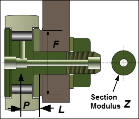
The Stud is the shaft through the center of the bearing. It extends to one side of the bearing so you can fix it to the Follower. Support Flange and Dimension, F To sufficiently support the side plate of the bearing, the shoulder should be ground flat, and be larger than dimension F. Dimension 'F' is given in OEM catalogs. The material of the Follower must support the compressive stresses of the tightening torque - see below. Stud Diameter A metric stud usually has a 'shaft' tolerance of h7. This is a zero to negative tolerance. A imperial (inch) stud typically is oversized by approximately 0.025mm. Hole through Follower Metric Hole tolerance : JS7 (J7). This is a small plus and minus tolerance of the nominal hole size. Inch Hole tolerance : F7. This is a positive tolerance on the hole. In both cases, the stud should have a light press fit. |
Stud Stress The stress on the stud is a function of two parameters: •Tightening Torque : produces a Tensile Stress, σt. When the guidelines are followed, the tensile stress, σt , is approximately 100MPa. •Contact Load, P, produces a Bending Stress, σb The bending stress, is: σb = P.L.y/J σb = P.L./z Note: J, the second moment of area, is reduced when there is an oil-hole through the center of the stud.
Stud fails if: Total Stress = Bending Stress, σb + Tightening Stress, σt ≥ Tensile Strength, or Yield Stress, σyield σt + σb > σyield Rules of thumb: the total stress on the stud should be less than: • when load is static • when load is dynamic but uni-directional • when load is bi-directional and dynamic Thread fails if:... ...the nut becomes loose. This occurs when:
If the compression stress due to bending exceeds the tension stress due to the nut's tightening, the nut might become loose. To prevent the nut becoming loose, follow the tightening torque guidelines! Hexagonal Nuts Tightening Torques (EN ISO 4032). M6x1(3Nm); M8x1.25(8Nm); M10x1(15Nm); M12x1.5(22Nm); M16x1.5(58Nm); M18x1.5(87Nm); M20x1.5(120Nm); M24x1.5(220Nm); M30x1.5(450Nm) |
|
Follower-Rollers - General Installation Requirements
•Install the oil plug, with a small mandrel (if you are not going to re-lube it) to prevent the rolling elements being contaminated by the ingress of dirt. •Insert a pin into the lubrication hole that is transverse to the shaft to prevent the stud rotating. •Locate the lubrication hole that is transverse to the shaft in the unloaded direction - so it is in nominally compression. |