Gear-Pair with an Orbiting Center

<< Click to Display Table of Contents >>

Navigation:  Getting Started Tutorials - MechDesigner > Tutorial 14: Gear-Pairs / Rack-Pinions > B: Orbiting Gear Centers >

Gear-Pair with an Orbiting Center

B: Orbiting Center Gear-Pairs

Arrangement 1: Orbit a gear around the outside of a fixed-gear - External Mesh.

Arrangement 2: Orbit gear around the inside of a fixed-gear - Internal Mesh.

Epicyclic Gear-Pair - Prepare

Three Lines in three Parts

Three Lines in three Parts

STEP 1: Three Lines in Three Parts

1.Edit a kinematically-defined Part (usually the Base-Part) with the Part-Editor.

2.Add a LineRed-14-1b ; and add Constraints and Dimensions, as needed.

3.Close the Part-Editor

4.Add two Parts Red-14-3Red-14-2

5.Join the start-Point of LineRed-14-4 in PartRed-14-3 to the start-Point of LineRed-14-1b with a Pin-JointRed-14-5

6.Join the start-Point of LineRed-14-7 in PartRed-14-2 to the end-Point of LineRed-14-4 in PartRed-14-3 with a Pin-JointRed-14-6

All Lines and or CAD-Lines

Dimension to Line for Gear-Centers

Dimension to Line for Gear-Centers

STEP 1: Add a Dimension

Edit PartRed-14-3 in the Part-Editor

You can see that there is a DimensionRed-14-8 along the CAD-Line - LineRed-14-4 - in PartRed-14-3

Exit the Part-Editor

Model is prepared for Epicyclic Gears

Model is prepared for Epicyclic Gears

STEP 3: Add a Motion-Dimension FB other FBs

1.Kinematic FB toolbar > Add a Motion-Dimension FB

Click Pin-Joint Red-14-5

Click LineRed-14-1

Click LineRed-14-4

2.Click OK-tiny-13-17 in the Command-Manager.

3.Kinematic FB toolbar > Add a Motion-Dimension FB

Add Gear-Pair

Command-Manager for Add Gear-Pair

Command-Manager for Add Gear-Pair

STEP 1: Start the Add Gear-Pair command

GST-Icon-AddGearPair

1.Expand the Machine-elements toolbar

2.Click Add Gear-PairRed-14-2

The Command-Manager has four selection-boxes.

STEP 2: Select the four elements

See images above for element numbers

1.Green Line on Gear 1: LineRed-14-1b - it is in a Part that is kinematically-defined

2.Blue Line on Gear 2: LineRed-14-7 in PartRed-14-2 that is NOT kinematically-defined

3.Green Line Joining Gears: LineRed-14-4 in PartRed-14-3 that is kinematically-defined - that will join to the Gear centers

The Part-Editor opens to edit PartRed-14-3

4.Center Distance Dimension: Length Dimension of LineRed-14-4

STEP 3: Complete the command

1.Click OK-tiny-11-15 to complete the command


Epicyclic-Gears

Epicyclic-Gears

The default Gear-Pair has an External Mesh, and the gears have equal number-of-teeth.


In the Command-Manager we use the terms:

Green Line for a Line in a Part that is kinematically-defined.

Blue Line for a Line in a Part that is NOT kinematically-defined.

Videos

Video - Prepare for Epicyclic Gear-Pair

Prepare for Add Epicyclic-Gears

Video - Add Epicyclic Gear-Pair

Add Epicyclic-Gears

Edit Epicyclic Gear-Pair

Edit Number-of-Teeth, Module and Mesh

GST-T14-B1-A

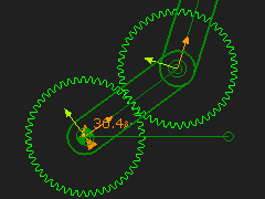
Default Gear-Pair: Orbiting Gear rotates around the outside of a Sun Gear

The default Gear-Pair has:

an External Mesh form, and the number-of-teeth on each gear are equal.

a module that minimizes a change to the length of the Line that is the Line-of-centers.

Length of the Line-of-Centers

= Module × ( (Number-of-Teeth Gear 1 + Number-of-Teeth Gear 2) ÷ 2).
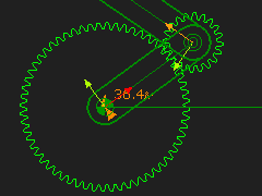
GST-T14-B1-B

Edit the Number-of-Teeth and Module:

Gear 1 = 60

Gear 2 = 20

Module = 2

Length of Line-of-Centers

= Module × ((Number-of-Teeth Gear 1 + Number-of-Teeth Gear 2) / 2)

= 2 × ((60 + 20)÷2) = 80mm

GST-T14-B1-C

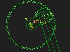
Edit the Mesh - Orbiting Gear rotates inside the Stationary Gear.

Internal Mesh

When the Gears have a different number-of-teeth, it is possible to move the smaller gear to the inside of the larger gear.

Length of the Line-of-Centers with an Internal Mesh is:

= 2 × ((60 – 20)÷2) = 40mm