B: ORBITING GEARS
Planetary Gear-Trains
A Planetary Gear Train has:
•one or more gears (Planets) held in a Carrier.
•Planet gears that rotates about their own axes and also rotate about the central axis of the Sun and Annulus Gears.
Planetary Gear Design Arrangements
|
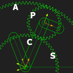
The typical arrangement of the gears is shown to the left. There is a: •Sun-Gear (S), with External Teeth •Annulus-Gear (A), with Internal Teeth, with the same center as the Sun Gear. The Annulus is also called the Ring. •Planet-Gear(P), usually more than one gears that engage with the Sun and Ring Gear •Carrier (C), which “carries” the Planet gears. The Gear-Ratio of a Planetary gear-box is a function of which gear or carrier is fixed to the frame. See YouTube video here: http://youtu.be/hXTzO1UXnLs Note:
|
|
 Planetary Gears |
Planetary Gears There are six design variations with one stationary gear. The three common variations are: •Variation 1: The Carrier (C) is the Input; the Sun (S) is Stationary; the Output is (A). •Variation 2: The Sun (S), is the Input; the Carrier is Stationary (C); the Output is (A). •Variation 3: The Sun (S), is the Input; the Annulus (A) is Stationary; the Output is (C). Other three other Variations are: •Variation 4: The Carrier (C), is the Input; the Annulus (A) is Stationary; the Output is (S). •Variation 5: The Annulus (A), is the Input; the Carrier (C) is Stationary; the Output is (S). •Variation 6: The Annulus (A); is the Input: the Sun is Stationary (S); the Output is (C). ω = Number of Sun-Teeth / Number of Annulus-Teeth |
VARIATION 1: Driving Carrier (C) ; Driven Annulus (A) ; Stationary Sun (S)
Planetary Gears - Variation 1 |
This is a video of Variation 1 |

Prepare Gear-Pair 1
|
STEP 1: Add a Line to the Base-Part
|
|
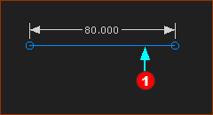
 Dimension to Line for Gear-Centers |
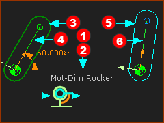
STEP 2: Add a rotating-Part that is kinematically-defined
|
|
 Model is prepared for Epicyclic Gears  that is NOT kinematically-defined") rotating-Part(6) that is NOT kinematically-defined |
STEP 3: Add a Line to the rotating-Part
|
|
STEP 4: Add a Part to the end of the rotating-Part
|
Add Gear-Pair 1
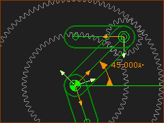
 Epicyclick Gear-Pair ; Z1=60 ; Z2=20 |
See Add a Gear-Pair with an Orbiting center
The Length of the Line-of-Centers should be 40mm Length of Line-of-Centers with External Mesh |
Prepare Gear-Pair 2
 Planetary-Prepare |
STEP 1: Add a Part to the end of the Line
|
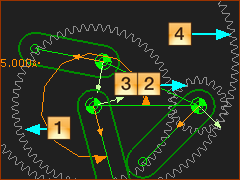
Add Gear-Pair 2
 Gear-Pair 1 and 2 |
STEP 1: Add Gear-Pair 2
|
|
![Gear-Pair 1 [1,2] and Gear-Parr 2 [3,4]](gst-14-b-208.png "Gear-Pair 1 [1,2] and Gear-Parr 2 [3,4]") Gear-Pair 1 [1,2] and Gear-Parr 2 [3,4] |
STEP 2: Edit Gear-Pair 2
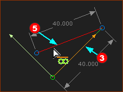
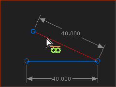
The length of the Line-of-Centers should be 40mm The Length of Line-of-Centers with Internal Mesh |
|
|
STEP 3: Make the Line-of-Center of Gear-Pair 2 collinear with Line-of-Center of Gear-Pair 1
|
|
|
RESULT Planetary Gears of Variation 1 |
VARIATION 2: Driving Sun (C) ; Driven Planet (S) and Annulus (A), Stationary Carrier.
Planetary Gears - Variation 2 |
This is a video of Variation 2 |
Prepare Gear-Pair 1
|
Prepare the model for a Simple Gear-Pair
|
Add Gear-Pair 1
 Simple Gear-Pair |
STEP 1: Do Add Gear
|
|
 Gear 1=60T ; Gear 2= 20T |
STEP 2: Edit Gear-Pair 2
The length of the Line-of-Centers should be 40mm The Length of Line-of-Centers with Internal Mesh |
Prepare Gear-Pair 2
 Line with Dimension |
STEP 1: Add a Line to the end of the Line-of-Centers in Gear-Pair 1
|
|
 Part for Gear2 in Gear-Pair 2 |
STEP 2: Add a Part for Gear-2 in the Gear-Pair 2
|
Add Gear-Pair 2
 Gear-Pair 1 and 2 |
STEP 1: Add Gear-Pair 2
|
|
|
STEP 2: Edit Gear-Pair 2
The length of the Line-of-Centers should be 40mm The Length of Line-of-Centers with Internal Mesh |
|
|
STEP 3: Make the Line-of-Center of Gear-Pair 1 collinear with Line-of-Center of Gear-Pair 2
|
|
|
RESULT Planetary Gears of Variation 2 |
VARIATION 3: Driving Sun (S) ; Stationary Annulus (A) ; Driven Carrier (C);
Planetary Gears - Variation 3 |
This is a video of Variation 3 |
Prepare Gear-Pair 1
|
STEP 1: Add Line to the Base-Part
|
|
Dimension to Line for Gear-Centers |
STEP 2: Add a rotating-Part that is kinematically-defined
|
|
Model is prepared for Epicyclic Gears rotating-Part(6) that is NOT kinematically-defined |
STEP 3: Add a Line to the rotating-Part
|
|
STEP 4: Add a Part to the end of the rotating-Part
|
Add Gear-Pair 1
 Epicyclick Gear-Pair ; Z1=100 ; Z2=20, |
See Add a Gear-Pair with an Orbiting center
The Length of the Line-of-Centers should be 40mm Length of Line-of-Centers with Internal Mesh |
Prepare Gear-Pair 2
 Prepare for Gear-Pair 2 |
STEP 1: Add a Part to the end of the Line
|
Add Gear-Pair 2
 Gear-Pair 1 and 2 |
STEP 1: Add Gear-Pair 2
|
|
Gear-Pair 1 [1,2] and Gear-Parr 2 [3,4] |
STEP 2: Edit Gear-Pair 2
The length of the Line-of-Centers should be 40mm The Length of Line-of-Centers with Internal Mesh |
|
|
STEP 3: Make the Line-of-Center of Gear-Pair 2 collinear with Line-of-Center of Gear-Pair 1
|
|
|
RESULT Planetary Gears of Variation 3 |