Add a Cam to the Epitrochoid Curve
You will see the difference between a 2D-Cam when the Velocity equations you enter are correct, and not correct.
A 2D-Cam is a good example. To calculate the XY-Coordinates of a 2D-Cam, MechDesigner must know the velocity of the Follower relative to the Cam.
In this Tutorial, we symbolically differentiate the X and Y position equations - see Step 18.1 - to enter the velocity equations into the Math FB
MechDesigner calculates the Position,Velocity, and Acceleration (motion-values) of all Points that are kinematically-defined. Hence, if we had used an Gear-Pair, to generate the Epitrochoid Path, we would not need to calculate the Position,Velocity, and Acceleration values.
We are using a Math FB to generate the motion-values as an example of how we can use a Math FB.
The Parametric-Equations for the X and Y-axis Velocity Components
Symbolically differentiate the X and Y Parametric Equations for the Epitrochoid-Curve with respect to Θ.
The Parametric Equations for the X velocity and Y velocity are
PXvel = -(a+b)*sin(Θ) + h*((a+b)/b)*sin(((a+b)/b)*Θ)
PYvel = (a+b)*cos(Θ) - h*((a+b)/b)*cos(((a+b)/b)*Θ)
As before we must replace:
a with p(0) ; b with p(1) ; h with p(2) ; Θ with p(3)
In the Math FB, the equations are:
Q0[Vel] = -(( p(0)+p(1))*sin(p(3))) + p(2)*(((p(0)+p(1))/p(1)))*sin((( p(0)+p(1) ) / p(1)*p(3) ))
Q1[Vel] = ((p(0)+p(1))*cos(p(3))) - p(2)*(((p(0)+p(1))/p(1)))*cos(((p(0)+p(1))/p(1)*p(3)))
Remember, you can cut and paste these equations as the Velocity Equations in the Math FB.
|
|
Enter the Parametric Equations for the Velocity Components in the Math FB
 Position and Velocity Equations |
These are the 6 equations for the two output-connectors
•Equations 1 & 2: Position and Velocity of the X -axis
•Equations 4 &5: Position and Velocity for the Y-axis
•Equations 3 & 6: Default - acceleration for X-axis & Y-axis respectively - not yet entered. |
|
|
|
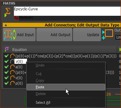
Cut and paste the Parametric-Equations into the Math FB dialog.
In your browser:
1.Highlight the equation
2.Right-click
3.Click Copy in the contextual menu
In the Math FB dialog
4.Click, pause, click the equation you want to replace
The equation box must be active, and ready to enter the equation as you would normally - see image to the left.
5.Right-click the equation
6.Click Paste
CTRL+V does NOT work.
Paste does work.
|
|
Add a 2D-Cam
The two Sliders move with the parametric equations to generate the Epitrochoid Curve
But, can we add a 2D-Cam and get its coordinates?
We will find that if the Velocity equations are not correct, the Cam will not be correct.
|
|
|
Add a Follower to the Slider-Y of the Piggyback Sliders
1.Mechanism-Editor : Edit Slider-Y Part
2.Part-Editor : - Drag in the graphics-area
3.Part-Editor: - Click the Circle to define its radius.
4.Part-Editor : - Click the center-Point of the Circle and the Y-axis ; again: its center-Point and X-axis
5.Part-Editor : Exit the Part-Editor
6.Mechanism-Editor : : Click the Circle, Click  in the Command-Manager. in the Command-Manager. |
|
Add a 2D-Cam
1.Mechanism-Editor: Click Machine element > Add 2D-Cam
The Command-Manager has two selection-boxes:
2.Mechanism-Editor: Click the Base-Part as the Cam-Part
3.Mechanism-Editor: Click the Profile - the Follower-Profile
4.Mechanism-Editor: Click in the Command-Manager |
|
|
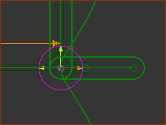
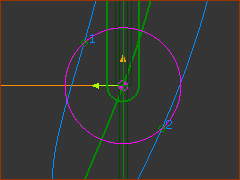
In the image above, look closely at the Cam and the Follower-Profile.
1.and again, to start then stop the machine-cycle
or
1.Drag the Master Machine Angle to a different Machine Angle
You can see the contact between the 2D-Cam and the Follower.
The 2D-Cam is not correct.
|
|
|
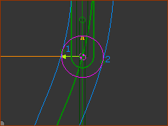
Check and correct the Velocity Equations in the .
Now, the 2D-Cam is correct.
Now you can get the Cam-Coordinates in the usual way - with a Cam-Data FB.
|
|