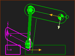
Design of a Spatial Mechanism that is common in Packaging Machines
Spatial mechanisms are common in packaging, assembly, and textile machines. The most common design is one in which the Parts of the kinematic-chain are on Mechanism-Planes that are perpendicular(⊥) (normal, orthogonal) to each other.
Design a Spatial Mechanism
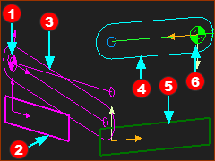
1.About the Ball-Joint and Connecting-Part 2.Add a Part and two Ball-Joints to make the Part a Connecting-Part 3.Edit the Length of the Connecting-Part 4.Edit the 'diameter' of the Connecting-Part 5.Edit the 'diameter' of the Ball symbol 6.Edit the offset of the Ball-Joints from each Mechanism-Plane |
Reminder:
All dyads have two Parts and three Joints.
It is helpful to think of the dyad as:
Joint - Part - Joint - Part - Joint
The middle joint in the dyad joins the two Parts together.
The other two joints in the dyad join each of the Parts to two other Parts.
Video:
See also: Ball-Joint Mounting Configurations.
|
Add Ball-Joint to constrain a Point (in one Part) to be coincident with a Point (in a different Part). |
|
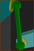
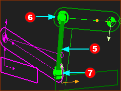
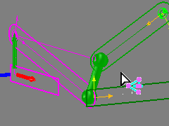
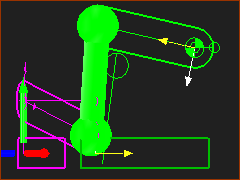
Use the Ball-Joint to construct a two dyads: •SSR (Spherical-Spherical-Revolute) - equivalent to Ball-Joint — Ball-Joint — Pin-Joint •SSP (Spherical-Spherical-Prismatic) - equivalent to Ball-Joint — Ball-Joint — Slide-Joint One of the two Parts in the SSR and SSP dyad has two(2) Ball-Joints -. The term we use for the Part with two Ball-Joints is the Connecting-Part. The image is a Connecting-Part with a Ball-Joint at its ends. |
Before we add a Connecting-Part and the two Ball-Joints we must prepare a kinematic-chain in two different Mechanism-Editors. |
||
|
STEP 1: Add a Mechanism and then Geometry to the Base-Part
|
|
|
STEP 2: Add a Rocker with a Motion
|
|
|
STEP 3: Edit the Length of the Part
STEP 4: Edit the Motion to have a range of 20º |
|
|
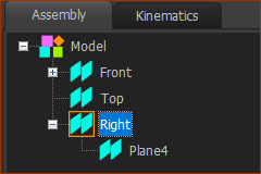
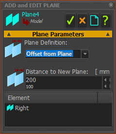
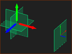
We need a new Mechanism-Editor (MECHANISM B). We will add it to a new Plane. The new Plane is offset from the Right Plane in the Model-Editor. STEP 1: Add the new Plane
|
|
|
||
|
STEP 2: Add the new Mechanism-Editor
You jump immediately to the new Mechanism-Editor - MECHANISM B |
|
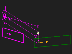 'Show other kinematic and sketch-elements' |
|
|
|
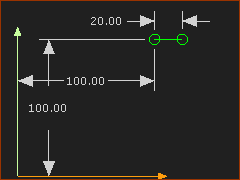
STEP 3: In Mechanism-B - edit the Base-Part to locate a Pivot-Point.
|
|
|
STEP 4: Add a Part and Define its Length.
This Part is not kinematically-defined. It is a Free-Part. |
|
|
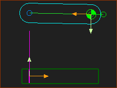
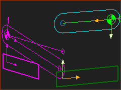
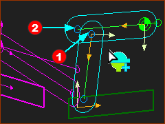
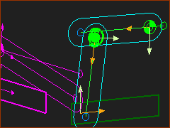
View MECHANISM A from MECHANISM B. Mechanism A The a Rocker Mechanism B The Free Part |
Add the Connecting-Part and two Ball-Joints.
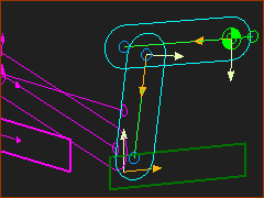
In MECHANISM B: Add a Part. It is Completely Free Part When we join it to other Parts with Ball-Joints, it has the derived-name of Connecting-Part. |
||||||
|
STEP 1: In Mechanism B add a Completely-Free Part
|
|||||
|
... STEP 2: Add Ball-Joint #1
|
|||||
|
||||||
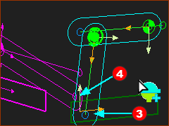
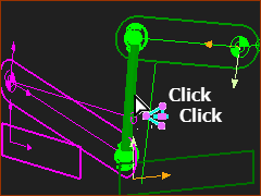
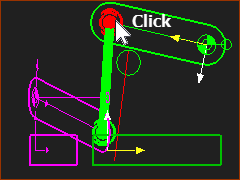
When you click Point •The two Points do NOT snap together •The end of the Part that will be the Connecting-Part has a Ball-Joint You must add Ball-Joint #2. One of the Points in Ball-Joint #2 is from the Mechanism-Editor-A. STEP 3: Add Ball-Joint #2
|
||||||
|
||||||
|
Now, in the graphics-area:
|
|||||
|
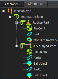
Kinematics-Tree Kinematics-Chain now includes an R-S-S dyad. Each S is a Spherical-Joint. They are the Ball-Joints. Note Mechanism B began with a Free-Part and a Completely-Free Part. After we add the two Ball-Joints they become the two Parts in the S-S-R dyad. |
|||||
It is easy to edit a Connecting-Part. It is easier to enable Show other Kinematic and sketch-elements to show the sketches of other Parts, even in the Part-Editor. |
|||
|
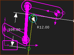
STEP 1: Edit the Length of the Connecting-Part.
The Connecting-Part in the open in the Part-Editor. When the Part is open in the Part-Editor, it returns to the position it had before we added the Ball-Joints. |
||
|
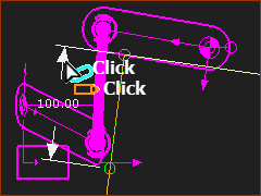
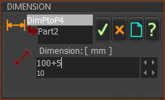
Remember, to edit a dimension, double-click the extension lines or arrowheads, but NOT the dimension number itself. The Dimension dialog is now open. To edit the dimension: •use your keyboard to enter a new value,
|
||
|
|||
|
The Connecting-Part is now 105mm long. |
||
You cannot import Solids or add Profiles/Extrusions to Connecting-Parts. You can add a Symbolic Rod as a MD-Solid between the Ball-Joints. |
||
|
The dimension of the first sketch-element we add to a Connecting-Part controls its Radius. STEP 1: Edit the Radius of the Connecting-Part
The Connecting-Part in open in the Part-Editor.
|
|
|
While the Connection-Part is open in the Part-Editor, it returns to the position it was at before we added the Ball-Joints.
|
|
|
To see the Symbolic-Radius for the Connecting-Part:
The Connecting-Part is still not attractive! |
|
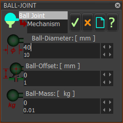
Use the Ball-Joint dialog to edit parameters that change the: •Appearance •Kinematic motion-values •Kinetostatic force values |
|||
|
STEP 1: Hide Solids
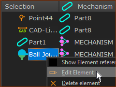
STEP 2: Open the Ball-Joint dialog the Ball-Joint dialog.
The Ball-Joint dialog is now open.
|
||
|
|||
|
Ball Joint dialog Ball Diameter (mm) The diameter of the Symbol for the Ball-Joint. You must use Visibility toolbar > Show Solids in Mechanisms to see the Ball-Joint symbol. Ball Offset from Plane (mm). Ball-Joints frequently do not lie on the Mechanism-Plane. When the Ball-Joints are not on the Mechanism-Plane, the kinematic analysis changes. See Also: Ball-Joint configurations Ball Equivalent Mass (kg) 0.03 (30 grammes) MechDesigner calculates Planar Forces. Enter the mass of the Ball-Joint. This mass is 'referred to' the Ball-Joint from the kinematic-chain in the other Mechanism. |
||
|
STEP 1: Show Solids
|
||
