Application Settings dialog
Use the Application Settings dialog to edit your working environment.
We save your settings for you when you exit MechDesigner.
Different users on the same computer can save and load their settings with the Save and Load buttons.
See also: Themes and Styles
Open the Application-Settings dialog
You can open the Application-Settings from the Edit menu or the Edit toolbar:
1.Click Edit toolbar > Application Settings Icon

Edit toolbar > Application-Settings
The Application--Settings dialog is now open.
The Application Settings dialog:
 Application-Settings dialog |
There are five tabs in the Application Settings dialog. GeneralNumber FormatGraphicsAccessibilityAuto-ProfilesLoad and Save buttons: To open and apply a style that contrasts well with a Theme. We have prepared a style for each theme. You can also save your own settings to the same style, or a style with a new file-name. See more: Themes and Styles |
Application Settings tabs
 General
|
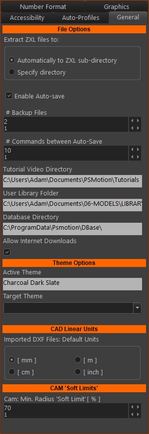
File Options Extract Files in .ZXL to ...: The ZXL file has all of the model's files. When you open a ZXL file you can: ◉Create a sub-directory automatically (name is the ZXL file-name) ◉Specify ZXL output directory. I recommend this option. I enter the same directory as the ZXL file. Enable Auto-save check-box (Default is checked) Save the model before Auto-save begins. ❑Enabled: Continually save the model to the same file-name. ❑Disabled: Save when YOU want to save the model Each auto-save: 1.Renames the file-name.CXL and .MTD files to file-name.~CXL and .~MTD 2.Saves the model as file-name.CXL and .MTD # Backup-Files: A backup-file is made automatically when you open a MechDesigner file. The backup-files use as file-extensions: .CXL.1, .CXL.2, ... and .MTD.1, .MTD.2, ... # Commands between Auto-Save To start auto-save, you must first save the model with File menu > Save. Theme Options Note: different Themes change the border colors, with contrasting toolbar icons, and different dialog colors. Active Theme : the Theme that you see when you start MechDesigner. Target Theme : drop-down box to select a different Theme: •Windows10 , Charcoal Dark Slate, ... Load button: to open and apply a style that contrasts well with a Theme. We have prepared a style for each theme. Save button: to save your settings to a style file-name. See more: Themes and Styles CAD Linear Unit Usually, select the units that are the same as the original drawing. Cam 'Soft Limits' Cam: Minimum Radius Soft Limit Recommended: 150% (Cam Radius-of-Curvature ÷ Cam-Roller Radius ) × 100 % In the graphic-area, the cam-profile becomes red at the places where the: Cam Radius-of-Curvature < 'Minimum Soft Limit' % × Cam-Roller: Radius |
Number Format
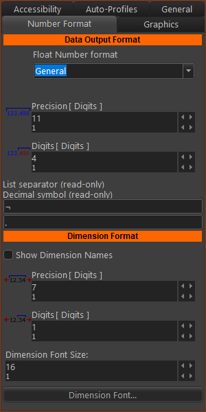 |
Data Output Format For Graph data and Cam-Coordinates that you can save from the model. Float Number Format: See here (Internet Link) about number formats: General, Exponent, Fixed and Number. Precision and Digits - see below Dimension Format Data format of dimensions in the graphic-area Precision and Digits - see below Dimension Font Size - Recommended : 13 Precision: The total number-of-digits before the number is rounded. Digits: The number-of-digits after the decimal mark.
Note: Usually Precision # > Digits # |
|||||||||||||||||||||||||||||||
Graphics
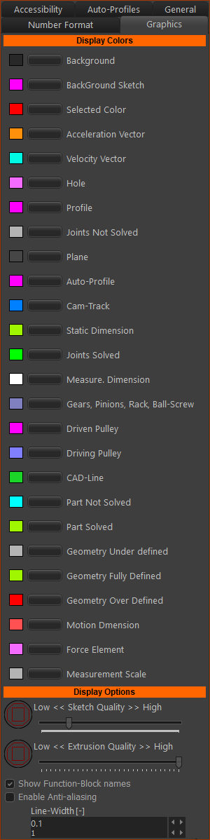 |
Display colors Change the color of many elements. Use each button to open the Windows® color 'picker'. We continue to add elements to the list.
Display Options quality: Low < Quality > High Use the 'Quality' slider to edit the drawing accuracy of various symbols and sketch-elements. Display Function-Block Name check-box Click the check-box to display the name (as given in the Assembly-Tree) above each Function-Block in the graphic-area. Anti-aliasing check-box Click the check-box to display kinematic and sketch-elements with aliasing on or off. Graphic-Line Width I find the best value is 0.8. |
|
 Show Function-Block Captions  Hide Function-Block Captions |
||
Show Function-Block Name Enable to see the element-name above each Function-Block in the graphic-area. Enable Anti-aliasing If you Enable Anti-Aliasing, Gears look terrible with anti-aliasing. Lines look OK. |
Accessibility
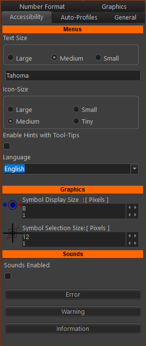 |
Menus Toolbar Icon Size Click the size to suit your display and eye-sight. Recommended : Medium Text Size Click the size to suit your display and eye-sight. Recommended: Medium Language English: English Enable Hints with Tool-Tips Hints If you do not need the hints, clear the Enable Hints with Tool-Tips check-box. The hints always show in the Feedback-Area. |
Graphics Symbol Display Size (Pixels): (5) The size of the symbols of the elements in the graphic-area, such as dimension, input and output-connectors, Part-Outlines and Part axes. Symbol Selection Size (Pixels): (6) The size of the pointer 'pin-head'. The larger this number the easier it is to select element. But, you may select more than one element. |
|
Sounds Enable Sounds: to let you listen to a sound when there is a new message in the Message Area in the Feedback-Area. Click the buttons to hear the sound for each message. Note: I do not Enable Sounds as there are many messages for each command. |
Auto-Profiles
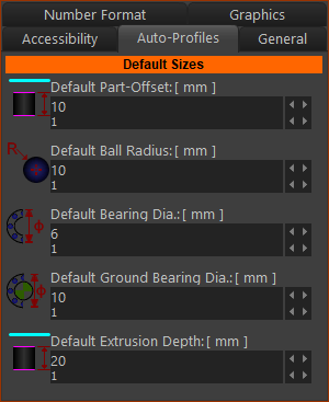 |
Default Sizes Set these sizes in proportion to your models. Default Ball-Joint Radius This parameter gives the default radius of the Ball-Joint symbol. See Ball-Joint dialog Default Bearing Diameter / Default Grounded Bearing Diameter The dimensions used for the arcs at each end of an Auto-Profile when you use the Solid toolbar > Auto-Profile command. Edit the Part later to edit the dimension, if necessary. See Add Auto-Profiles (Mechanism) command. Default Extrusion Depth The default Extrusion-Depth of Extrusions (along the Z-axis of the active editor) when you use the Add Auto-Profile and Add-Profile commands. Edit the Extrusions later to edit the Extrusion-Depth, if necessary. See: Extrusion dialog |