How to export a Cam to SolidWorks or Solid Edge
Calculate the coordinates of the cam profile with a Cam-Data FB.
You can calculate the cam profile as a series of Points or as a series of BiArcs.
| To export the cam profile data to SOLIDWORKS from MechDesigner as a series of Points |
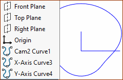
1.Make sure SolidWorks is open, and a Part document, existing or new, is the active document. 2.Open a Cam-Data dialog 3.Link a 2D-Cam to the Cam-Data FB 4.Calculate the Cam-Coordinates at Equal increments of the Master Machine Angle - say 360 for a typical plate size of cam 5.Click the “Send to SolidWorks” button in the Cam-Data FB toolbar The data in SolidWorks is a Curve feature. |
|
 |
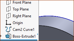
The Curve feature is on the XY-Plane, which is the Front View in SOLIDWORKS. Note: To move the Curve feature to the XZ or the YZ Plane. In the Cam-Coordinated dialog: 1.Save the Data as a SLDCRV file-type (in the Cam-Data FB > Save ) 2.Edit the data in Excel®, and swap the X-data, or Y-data, and the Z-data 3.Save the data to NotePad® In SOLIDWORKS: 4.Click Insert menu > Curve > Curve Through XYZ Points 5.Import the data, and close the Curve feature dialog 6.Select a Plane that is coplanar or parallel to the Curve feature 7.Start a sketch on the Plane 8.Use Convert Entities in SolidWorks® sketch editor 9.Extrude the Curve. You can see the Cam does not have any facets. |
 |
|
To import into other CAD
1.Open the file, with file-type as... *.TXT 2.Select delimiter, as a ',' or 'tab'. You want the 'X' and 'Y' Cam Points in separate columns. Experiment with the import options if necessary. 3.Tidy up the data, remove headers etc. 4.Move all the data so the first X Point starts at Cell A1, and the first Y Point at B1. 5.If necessary, make the first and last X and Y points equal - you may need to add a row of data. 6.Add a Column for the Z-Axis, and fill it with Zeros (0). Experiment as necessary. 7.If necessary, scale the Cam-Data to the units you are working in your CAD. 8.Save your data to an Excel® spreadsheet. 9.Save your Data to a NotePad® file. You may be able to import the Excel® or the NotePad® file into your CAD. |
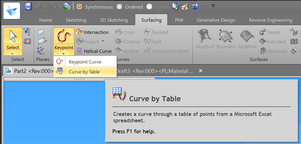
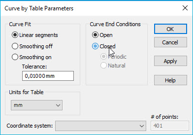
Insert Object / Curve by TableSelect: 1.Surfacing tab → Curves group → Keypoint → Curve By Table 2.On the Insert Object dialog, set the Create from File option and click OK. Browse to and Open your Excel® spreadsheet Curve by Table uses an Excel spreadsheet to define a construction curve. The spreadsheet, which is embedded in the Solid Edge document, allows you to more easily import your data.   Solid Edge: Curve by Table Parameters dialog
Curve by Table Parameters Curve Fit •Linear Segment Creates line segments between the data points in the table. •Smoothing Off Applies the direct curve fit method to the data points in the table. Using this method, the curve passes directly through the points. •Smoothing On Applies the 'least squares' curve fit method to the data points in the table. When you select this option, you enable the tolerance drop list. Using this method, the curve path is controlled by the tolerance value and does need to touch the points. •Tolerance Allows you to specify a tolerance for the Smoothing On option. It is the maximum distance the curve can deviate from the points. Curve End Conditions •Open To specify an open curve. For example, the first and last data points do not touch each other or any part of the curve. •Closed To specify a closed curve. For example, the first and last data points can touch one another or any part of the curve. When this option is set, the Periodic and Natural options are available. •Periodic Connects the first data point with the last data point to make a smooth tangent closed curve. •Natural Creates a closed curve without a tangent condition. Note: The Curve by Table feature fails if the first and last data points in the spreadsheet are coincident. If you select 'Closed', delete the last point in the table if it is coincident with the first point. Coordinate System Allows you to select coordinate systems to offset the curve data to. Make the coordinate system prior to creating the curve through table of points. Number-of-points Records the total number-of-points in spreadsheet. Possible Problems with Curve by TableThe following are possible error messages resulting from Curve by Table: •Invalid Geometry: Edit Feature Inputs The data points in the spreadsheet are incorrect. Check the spreadsheet and make certain you have input at least two rows of X,Y,Z coordinates, have not skipped any cells, and have not entered data points that define a curve that runs back through itself either in 2D or 3D. •Curve Is Self Intersecting The curve runs back through itself in 2D or 3D. Change the data points in the spreadsheet. •Units Set Out Of Range The units are too large. Make sure the diameter of the model is less than five kilometers. •Curve By Table Feature Failed Closed and Periodic options are set on the Curve Table Parameters dialog, and the first and last data points in the spreadsheet are coincident. Change one of the coincident data points. |
Back to How to...