•one or more Arc and/or Line and/or Blend-Curves sketch-elements
•that you join end-to-end with an end-Point of one sketch-element merged to a start-point of a different sketch-element.
•arranged in an open or closed shape.
Add a Blend-Curve
In this tutorial, we merge*Blend-Curve with a Line and an Arc. The sketch will be an open sketch-path
* The end-Points and start-Points of the sketch-elements, not the sketch-elements themselves.
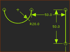
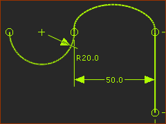
STEP 1: Add the Line and Arc sketch-elements
1.Edit the Base-Part
2.Geometry toolbar > Add Line (drag upwards), Add Arc (drag Right-to Left, then downwards)
3.Constraints toolbar > Add Horizontal
(1)Line; (2)end-Point of Line and start-PointArc; (3)start-Point / center-Point of Arc; (4)center-Point and end-Pointof Arc
4.Constraints toolbar > Add Dimension | Radius of the Arc = 20mm;end-Point of the Line to the start-Point of the Arc = 50mm; Length of the Line = 50mm
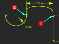
STEP 2: Add the Blend-Curve
1.ClickGeometry toolbar > Add Blend-Curve
Hover above the end-Point of theLine, mouse-button-down ...
.... +Drag ....
... to the start-Point of the Arc and mouse-button-up.
We merge for you the start-Point and end-Point of the Blend-Curve with the the start-Points and end-Points of the Line and Arc.
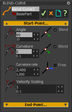
Notes: Default Blend-Curve dialogParameters
The Blend-Curve is a smooth curve whose parameters are its Angle, Radius of Curvature, Curvature-Rate and Velocity scale.
The Parameters control the Blend-Curve at the start-Point and end-Point and influence its overall shape.
Default Blend-CurveParameters
We use the Blend check-box to force each parameter to be numerically equal those of the sketch-element with which you merge its start-Point and/or end-Point.
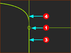
Start-Point
•Angle = 90º Angle of the end-Point of the Lineis vertically upwards. Therefore, Angle =+90º
•Curvature = 0. Radius of Line = ∞. Curvature = 1/ Radius = 1/∞ = 0
•Curvature Rate = 0. Curvature of Line is a constant. Therefore the Curvature-Rate = 0.
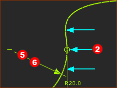
End-Point
•Angle = –90º (or 270º) : Angle of the start-Point of the Arc is vertically downwards. Therefore Angle = –90º (or 270º).
•Curvature = 50 :Radius of a Arc = 20mm. Curvature = 1/ Radius = 1/0.02m = 50.Therefore, Curvature = 50.
•Curvature Rate = 0. Curvature of the Arc = constant. Therefore, Curvature-Rate = 0.
Edit the Blend-Curve
Blend-Curve dialog - default
STEP 1: Open the Blend-Curve dialog
Note: You can open the Blend-Curve dialog from the Part-Editor and from the Mechanism-Editor.
The shape of the Blend-Curve is continuous with the sketch-elements to which it is merged.
•Angle = 90 : Equal to the angle of the Line
•Curvature = 0 : Equal to theCurvature of the Line
•Curvature Rate = 0 : Equal to theCurvature Rate of the Line.
Velocity-Scaling - this parameter is a way of inflating the Blend-Curve (similar to inflating a balloon)
STEP 2: Edit Blend-Curve dialog > Start/End Point > Curvature-Rate
Start-Point
1.Curvature Rate - disableBlend
2.Curvature Rate = 2400
End-Point
3.Curvature Rate, disable Blend
4.Curvature Rate =-3000
Click to close the Blend-Point dialog
The units of Curvature Rate are 1/m2.
Top-Tip
Rather than calculate values for Curvature Rate, it is easier to look at the shape of the Blend-Curve as you use the Spin-Box.
What is the best Blend-Curve?
It is not possible to know unless you know the application of the Blend-Curve.
This is the new shape for the Blend-Curve.
Curvature-Rate at the start-Point is 2400/m^2
Curvature-Rate at theend-Point is -3000/m^2
Add a Motion Path FB
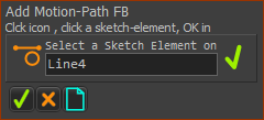
STEP 1: Add a Motion-Path FB
1.ClickKinematic FB toolbar > Add Motion-Path FB
2.Click the verticalLine
3.Click in the Command-Manager
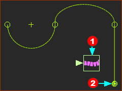
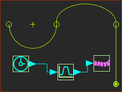
The graphics-area after STEP 1
Motion-Path FB
Motion-Point at the start-Point of the Line sketch-element
Note: Where is the Motion-Point?
When the sketch-path is an open sketch-path, the Motion-Point finds the sketch-element with a start-Point that is nearest to the sketch-element that you click.
STEP 2: Add Function-Blocks
1.Kinematic-FB toolbar > Add Linear-Motion FB
2.Kinematic-FB toolbar > Add Motion FB
3.Connect the Function-Blocks with wires, in the usual way.
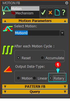
STEP 3: Edit the Output Data-Type of the Motion-FB
Motion (default) - connect the Motion FB to a Motion-Dimension FB.
The motion-values at the output move a Motion-Part to an Angle(degrees) or a Position(mm) relative to a sketch-element in a different Part.
Linear - connect the Motion FB to a Motion-Path FB.
The motion-value at the output from the Motion FB moves a Motion-Point along the sketch-path to a position equal to motion-value.
E.g. 90 at the output from the Motion FB and at the input to a Motion-Path FB moves the Motion-Point by 90mm along the sketch-path from its start-Point*.
Rotary- connect the Motion FB to a Motion-Path FB.
The motion-value at the output from the Motion FB moves a Motion-Point along the sketch-path to a position equal to (motion-value/360 * Total-Length)mm
E.g. 90 at the output from the Motion FB and at the input to a Motion-Path FB moves the Motion-Point((90/360) × Total-Length)mm along the sketch-path from its start-Point*.
* the start-Point of a sketch-path is the start-Point of the sketch-element you select. Experiment!
Video: Motion-Point moves by Total-Length * 90/360
STEP 4: Observe the Motion-Point when you cycle the model
1.Press ALT+C keys on your keyboard to cycle the model.
The default motion has a Rise of 90mm.
The Output Data-Type from the Motion FB is Rotary. Therefore, the Motion-Point moves by 90/360 (or 25%) of the total length of the sketch-path from the start-Point.
2.ALT+C again to stop the model (or Run toolbar > Cycle)
<<< Click to play the video
Motion rise from 0 to 360
STEP 5: Edit the Motion in MotionDesigner, to have a Y-axis range of 0 to 360
Position of the Motion-Point = (Input/360) × Total-Length
An input-range of 0-360 moves the Motion-Point from the start-Point to the end-Point of the sketch-path.
Video: Motion-Point moves by Total-Length * 360/360
STEP 6: Edit the Motion in MotionDesigner, to have a range of 0 to 359.99
Why 355.99?
When the motion-value is 360, the Motion-Point may wrap to the start-Point of the sketch-Path.
When the motion-value is 359.99, the Motion-Point will not wrap to the start-Point of the sketch-Path.
359.99 is near to the end-Point of the sketch-path.