The Oldham Coupling transmits power between shafts that are parallel and offset from each other.
A floating disc, in the middle of the coupling, has a raised rib on each face. Each rib is perpendicular(⊥) to each other. The raised ribs engage with slots in flanges on the input and output shafts.
The Oldham Coupling is a that is built with a:
1., and
2. |
|
|
The video is of an Oldham Coupling.
Input The Input – the Motion-Part
Output The Output Crank – rotates at the same constant speed.
Middle Disk This transmits power/torque from the Input to the Output Crank.
|
|
A kinematic-chain has a Motion-Part as an input.
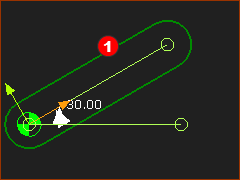
STEP 1.Add the Motion-Part – a Crank
1.Edit the Base-Part : : Drag to add the Line , , Close the Part-Editor
2.Mechanism-Editor: Click : drag to add the new Part.
3.Mechanism-Editor: Click : Click the start-Point of the new Part and the start-Point of the Line in the Base-Part.
4.Mechanism-Editor: Click Click the Pin-Joint the Line in Base-Part; the CAD-Line in Part. and  in Command-Manager in Command-Manager
5.Mechanism-Editor: Click : and click the graphics-area. Joint the FBs with a wire. You have a Crank |
|
|
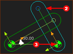
You must now add a dyad. Dyads always have two Parts and three Joints. Never forget this!
STEP 2.Add the dyad
Dyad: Part-2 and Joint-3
The output of the Oldham Coupling rotates.
1.Mechanism-Editor: Click  : Add a Part : Add a Part
2.Mechanism-Editor: Click  Partend-Point of the Line in the Base-Part. Partend-Point of the Line in the Base-Part. |
|
|
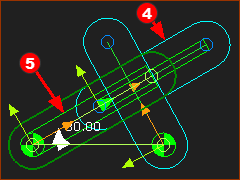
Dyad: Part-1 and Joint-1
1.Mechanism-Editor: Click  : Add a Part : Add a Part
2.Mechanism-Editor: Click 
a)Click the CAD-Line in the Part
b)Click the CAD-Line along the Crank |
|
|
Preparation for the middle Joint - Joint 2
Edit Part:  : Drag to add a Line, , : Drag to add a Line, ,
Close the Part-Editor
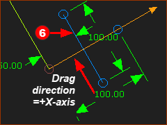
Note: The +X-axis is the direction you drag to the add the Line. - from its start-Point to its end-Point.
|
|
|
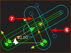
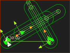
Dyad: Joint 2
|
|
Result:
The Oldham Coupling is Complete.
You can add Extrusions to the Parts to show the coupling as a Solid model.
Note: Part-1 (the Output-Part) may be 180º to the direction it is in this image. The direction of the +X-axis of the Output-Part is the same direction Line (start-Point to the end-Point) you add to make the Slide-Joint.
The +X-axis of a Line is the same as the direction you drag your mouse-pointer to add the Line.
|
|
|
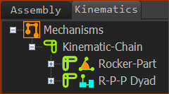
The Kinematics-Tree
One kinematic-chain with a Motion-Part - Rocker (Crank) - and an R-R-P dyad.
Note: this is the same dyad as the Scotch Yoke!
Oldham Coupling, you connect the R Joint to the Base-Part and the P-P Joints are internal to the kinematic-chain.
Scotch-Yoke, you connect the P Joint to the Base-Part, and the R-P Joints are internal to the kinematic-chain.
|
|
