Step 10.2: The Whitworth Quick Return Kinematic-Chain

<< Click to Display Table of Contents >>

Navigation:  Getting Started Tutorials - MechDesigner > Tutorial 10: Model Mechanical Devices >

Step 10.2: The Whitworth Quick Return Kinematic-Chain

A Whitworth kinematic-chain – or a Quick-Return kinematic-chain

A Whitworth Quick Return changes rotary movement to a back-and-forth movement. The Part moves faster in one direction than the other.  

This kinematic-chain has:

1.A Motion-Part – a Crank

2.Two dyads – an R-P-R and an R-R-P dyad

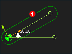
The video is of the Whitworth Quick-Return kinematic-chain.

Input: A Crank – the Motion-Part

Output: It slides quickly in one direction and slowly in the other direction. This is the termed Quick-Return.

STEP 1: Add the Input Part – a Crank
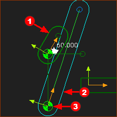
The CrankRed-14-1b is the input Part to the mechanism. See Tutorial 1, or

1.Mechanism-Editor: Kinematic elements > Add Part , Drag to add a Part

2.Part-Editor: Edit the Base-Part, Add a Horizontal Line , Exit the Part-Editor

3.Mechanism-Editor: Kinematic elements > Add Pin-Joint : Join the Part to the Base-Part with Pin-Joint

4.Mechanism-Editor: Add a Motion-Dimension FB to give the Angle of the Part relative to the Line

5.Mechanism-Editor: Add a Linear-Motion FB and connect it to the Motion-Dimension FB

GST-10-2-001

GST-10-2-WQR-001

STEP 2: Add dyad 1

Dyad 1: Part 1 and Joint 1

1.Part-Editor: Edit the Base-Part, Add a vertical line, from the start-Point of the Horizontal Line, Exit the Part-Editor.

2.Mechanism-Editor: Kinematic elements > Add PartRed-14-2 | Drag to add Part

3.Mechanism-Editor: Kinematic elements > Add Pin-JointRed-14-3 :

a.Click the start-Point of PartRed-14-2

b.Click the end-Point at the bottom of the vertical Line in the Base-Part

GST-10-2-WQR-002

Dyad 1: Part 2 and Joint 3

Continued... Add PartRed-14-4 and join it to the end of the CrankRed-14-1b.

1.Mechanism-Editor: Kinematic elements > Add Part | Drag to add a new PartRed-14-4

2.Mechanism-Editor: Kinematic elements > Add Pin-Joint

a.Click the end-Point of the CrankRed-14-2

b.Click the start-point of new PartRed-14-4

Dyad 1: Joint 2

Continued... Use Add Slide-Joint and select the Lines along the center of the two Parts that are not kinematically-defined.

1.Mechanism-Editor: Kinematic elements > Add Slide-Joint

a.Click the CAD-LineRed-14-6 along PartRed-14-4 - see above

b.Click the CAD-LineRed-14-7 along PartRed-14-2 - see above

A Slide-JointRed-14-8 completes the new R-P-R dyad.

The Parts are now kinematically-defined.

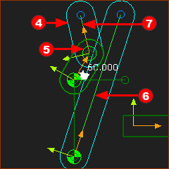
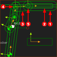
This is the basic Whitworth Quick Return kinematic-chain. The output Part moves quickly as the Crank (input) rotates from (counter clockwise) from 240 to 330 degrees, and more slowly as the crank rotates from 330 to 240 degrees.

GST-10-2-WQR-003

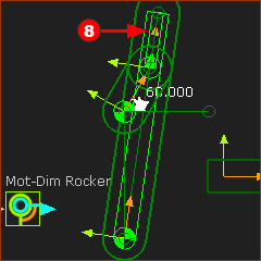
The length of the Crank and the distance between the Pin-Joints in the Base-Part give the 'Return Ratio'.

Return Ratio =

Crank Angle Range(Degrees) for one direction one

Crank Angle Range (degrees) for direction two

Experiment with the length of the Crank.

GST-10-2-WQR-004

Add dyad 2 - a dyad ALWAYS has two Parts and three Joints

1.Part-Editor: Edit the Base-Part, Add Horizontal Line Exit the Part-Editor

2.Mechanism-Editor: Kinematic elements > Add Part | Drag to add PartRed-14-1b

3.Mechanism-Editor: Kinematic elements > Add Slide-JointRed-14-2.

a.Click the CAD-Line in partRed-14-1b

b.Click the new Horizontal Line in the Base-Part

4.Mechanism-Editor: Kinematic elements > Add Part | Drag to add PartRed-14-3,

5.Mechanism-Editor: Kinematic elements > Add Pin-JointRed-14-4

a.Click start-Point of PartRed-14-3

b.Click end-Point of long Part (see dyad 1 )

6.Mechanism-Editor: Kinematic elements > Add Pin-JointRed-14-5

a.Click the start-Point of partRed-14-1b

b.Click the end-Point of PartRed-14-3

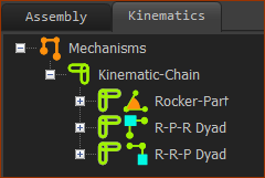
In the Kinematics-Tree, there is one kinematic-chain. It has a:

Rocker (the kinematic term we use for the Crank)

R-P-R dyad: Pin-Joint, Slide-Joint, Pin-Joint

R-R-P dyad: Pin-Joint, Pin-Joint, Slide-Joint

GST-10-2-WQR-005