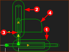
Step 11.1: Piggyback Sliders as XY Table

<< Click to Display Table of Contents >>

Navigation:  Getting Started Tutorials - MechDesigner > Tutorial 11: Two Degrees-of-Freedom Kinematic-Chains >

Step 11.1: Piggyback Sliders as XY Table

About Piggyback Sliders

This Piggyback Slider configuration has two Sliders:

Slider(A) : moves along the X-axis* of the Mechanism-Plane

Slider(B) : moves relative to Slider(A), and parallel to the Y-axis† of Slider(A)

The Piggyback Slider Configuration is only one way to model an XY-Path.  

You can also use a Motion-Path FB. See: Motion-Path and Blend-Curves.


* The two Sliders do not need to be parallel to the X-axis and Y-axis, or even orthogonal with each other. We use these directions for convenience only. They can equally be, for example, in the Radial and Tangential directions of a circle.

Mechanical Systems that have an XY Motion :

Piggyback Sliders - Gantry

Piggyback Sliders - are perpendicular (normal, 90º, orthogonal) to each other.

The motion of the motor has a linear relationship with the motion of the Slider.

A motor to drive each Slider - any linear-technology. E.g. Pulley & Belt, Ball-Screw & Nut, Rack & Pinion, Linear-Servomotor.

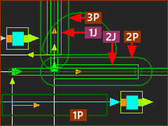
Piggyback Sliders and Dyads

Piggyback Sliders- are perpendicular (normal, 90º, orthogonal) to each other.

Connect dyads between the machine-frame and each Slider.

Add a Cam or Servomotor to drive each Part in the dyads that you connect to the machine-frame

Inverse-kinematics calculate the motions for the Followers or Servomotors to give the motions designed for the Piggyback Sliders - See Step 11.2

Translating Beam (a Part that moves on the Mechanism-Plane but does not rotate)

Piggyback Sliders to define the XY-Motion ONLY

Design a mechanism with a translating-beam that is not physically connected to the machine-frame or the Piggyback Sliders.

Look at this video.

Add Piggyback Sliders - Quick Instructions

GST-11-1-A-001

Quick Instructions:

1.Add Slider-XRed-14-1b to a horizontal Line in the Base-Part

2.Edit Slider-X. Add a Line that is parallel to the Y-axis

3.Add the Slider-YRed-14-2 to the Line that is parallel to the Y-axis of Slider-X.

4.Design the motions for each Slider.

5.Add a Trace-PointRed-14-4 to a PointRed-14-3 that moves with the Slider-Y.

6.Run menu  > Cycle to watch the Piggyback Sliders.

Add Piggyback Sliders - More Detailed Instructions

GST-11-1-A-002

Add Slider-X

1.Edit the Base-Part

2.Part-Editor: Geometry toolbar > Add Line , Constraints toolbar > Add Horizontal : Click the Line; Close the Part-Editor

3.Mechanism-Editor: Add a Part; Add a Slide-Joint between the Part and the Line in the Base-Part

4.Mechanism-Editor: Add a Motion-Dimension FB to control Slider - rename it to Slider-X

5.Edit the Motion-Dimension FB > Base-Value =50

6.Mechanism-Editor: Add a Linear-Motion FB and a Motion FB to the graphic-area Connect the FBs with wires.

7.Rename the Slider to Slider-X

GST-11-1-A-003

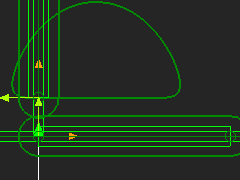
Edit Slider-X, Add a Vertical Line

1.Mechanism-Editor: Edit Slider-X : Part-Editor:  Edit length of the CAD-Line to 100mm

2.Part-Editor: Geometry toolbar > Add Line , Drag UPWARDS to add a new Line : Constraints toolbar > Add Vertical click the Line

3.Part-Editor: Geometry toolbar > Add Dimension : Edit the length of the Line to 100mm

4.Part-Editor: Constraints toolbar > Coincident , Click start-Point of the CAD-Line and the new Line

5.Close the Part-Editor

GST-11-1-A-004

Add the Slider-Y

1.Mechanism-Editor: Add a Part; Add a Slide-Joint between the new Part and the vertical Line in Slider-X

2.Mechanism-Editor: Add a Motion-Dimension FB to control the Position of Slider-Y.

3.Edit the Motion-Dimension FB > Base-Value =50

4.Mechanism-Editor: Add a Linear-Motion FB and a Motion FB to the graphic-area

5.Mechanism-Editor: Connect the FBs

6.Rename the new Slider to Slider-Y

GST-11-1-A-005

Get Motions for the Sliders

1.Mechanism-Editor: Edit the Motion FB connected to Slider-X to open the Motion FB dialog

2.Mechanism-Editor: Select Motion-X in the drop-down box.

3.Close the Motion FB dialog

4.Mechanism-Editor: Edit the Motion FB connected to Slider-Y to open the Motion FB dialog

5.Mechanism-Editor: Select Motion-Y in the drop-down box for Slider-Y

6.Close the Motion FB dialog

Show the Trace-Path:

7.Mechanism-Editor: Do Kinematic-element > Add Trace-Point , click a Point on Slider-Y

GST-11-1-A-007

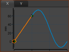
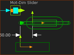
Run menu > Cycle (or ALT+C)


Motion-X

Blend-Point #

X - Input

Y - Output

Y-Vel

Motion-Law

1

0

0

180/s

Const. Vel.

2

120

(60)

(180/s)

Flex-Poly

1

360 / 0

0

(180/s

Const-Vel.

Link Motion-X to a Motion FB to connect a wire to the Motion-Dimension FB to move Slider-X.
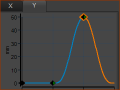
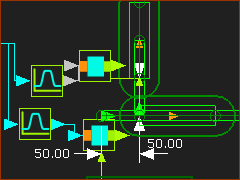
GST-11-1-A-008

Motion-Y

Blend-Point #

X - Input

Y - Output

Y-Vel

Motion-Law

1

0

0

0

Dwell

2

120

0

0

Poly 345

3

240

50

0

Poly 345

1

360 / 0

0

0

Dwell

Link Motion-Y to a different Motion FB and connect a wire to the Motion-Dimension FB to move Slider-Y.

Degrees-of-Freedom of Piggyback Sliders

GST-11-1-A-009

Degrees-of-Freedom and Mobility

Gruebler Equation

D = 3.(P-1) – 2.J  : P = Number of Parts (1 × Base-Part + 2 × Parts) ; J = Number of Joints ( 2 × Slide-Joints)

D = 3(3-1) – 2.2

D = 6 – 4 = 2

Mobility = # Degrees-of-Freedom(D) – # Motion-Dimensions = 2 – 2 = 0.

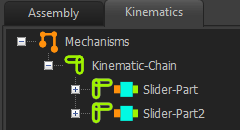
Kinematics Tree of Piggyback Sliders

GST-11-1-KT-PiggybackSliders

Kinematics-Tree for Piggyback Sliders.

One kinematic-chain

Two Sliders

Machines that use Piggyback Sliders

An XY-Gantry Robot

This Plotter moves a Pen along a slide, say the Y-axis slide. The X-axis carries the Y-axis slide.  The combined movement plots the drawing.

With this machine, there is an EXACT linear-equivalence between the XY-Path and the control positions of the slider motors. The system is Kinematically Linear.