Add 3× R-R-R dyads
Add a between each Piggyback Slider and the .
Drive, with a cam or servomotor, one in each dyad.
Dyads that we can use.
We can use any of five types of dyad. To keep the the model simple, we will add in this tutorial two R-R-R dyads.
1.First R-R-R dyad: Connect to Slider-X and the Base-Part
2.Second R-R-R dyad: Connect to Slider-Y and the Base-Part
|
STEP 1: Prepare the Parts to locate the R-x-R (Pin-Joints)
1.Edit the Base-Part: Add Horizontal Line to locate the R-x-x (Pin-Joint) in the Base-Part. Close the Part-Editor to locate the R-x-x (Pin-Joint) in the Base-Part. Close the Part-Editor
2.Edit Slider-X*, Add a Line to locate the x-x-R (Pin-Joint) in Slider-X. Close the Part-Editor. to locate the x-x-R (Pin-Joint) in Slider-X. Close the Part-Editor.
* Optionally, edit Slider-Y
|
STEP 2: We can now add the Parts and the Joints for the R-R-R dyad #1
3.Add two Parts. Add a Pin-Joint two join the two Parts two join the two Parts
4.Add Pin-Joint to join a Part to Slider-X (* or to Slider-Y) to join a Part to Slider-X (* or to Slider-Y)
5.Add Pin-Joint to join a Part to the Base-Part to join a Part to the Base-Part |
|
|
STEP 1: Prepare the Parts to locate R-x-R (Pin-Joints)
1.Edit the Base-Part - Add Horizontal Line to locate the R-x-x (Pin-Joint) in the Base-Part. Close the Part-Editor
2.Edit Slider-Y - Add a Line to locate the x-x-R (Pin-Joint) in Slider-Y. Close the Part-Editor |
STEP 2: Add the Parts and the 3x Joint the R-R-R dyad #2
3.Add two Parts.
4.Add a Pin-Joint two join the two Parts together
5.Add Pin-Joint to join a Part to Slider-Y
6.Add Pin-Joint to join a Part to the Base-Part |
|
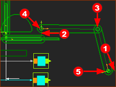
Question: Why an R-R-R dyad #3?
Answer: To drive the Piggyback Sliders from a position near the drive of dyad. #1. See the .
|
|
STEP 1: Prepare the Parts to locate the R-x-R (Pin-Joints)
1.Edit the Base-Part - Add Horizontal Line to locate where we join the R-x-x Pin-Joint in the Base-Part.
2.Edit a Part in dyad #2, Add a Line as a at 90º to the CAD-Line to locate where we add the x-x-R Pin-Joint .
3.Edit Slider-Y, Add a Line to locate where we join the R-R-R dyad to Slider-Y. Close the Part-Editor |
We can now add the R-R-R dyad #3
4.Add two Parts.
5.Add a Pin-Joint two join the two Parts
6.Add Pin-Joint to join one Part to the Bell-Crank
7.Add Pin-Joint to join a Part to the Base-Part |
|
|
|
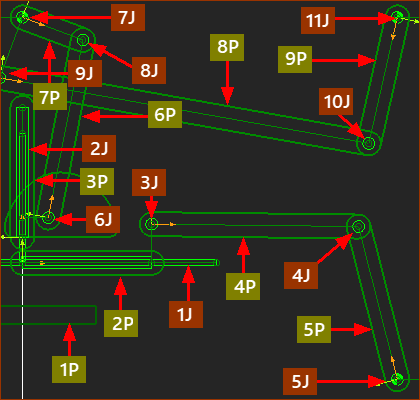
Now, the two Parts that drive the mechanism are near to each other.
This is more convenient place in the machine to add cams and servomotors.
Please watch the Video.
|
|
DEGREES-OF-FREEDOM
The design has 9 Parts
•1 × Base-Part
•2 × Slider
•3 × dyads = 6 Parts
The design has 11 Joint
•3 × dyads = 9 Joints
•2 × Sliders
Gruebler EQUATION:
F = 3(P–1) – 2J : (P = Parts ; J = Joints)
F = 3 × (9–1) – 2 × 11
F = 24 – 22 = 2
Degrees-of-Freedom = 2
|
MOBILITY
Mobility = Degrees-of-Freedom – Number of Motion-Dimensions.
Mobility = 2 – 2 = 0
|
|
How do we move the axes to follow the XY Path?
We can use:
•Servomotors : We would need to save the motions of the Parts that you want to drive to a text file, and format it for the servo controller.
•Cams and Followers : Add the Follower-Rollers and Cam-Shafts. See Tutorial 6.
The video is is of Piggyback Sliders, driven by 2D-Cams.
|
This video shows a more convenient configuration. Now two cams are on one cam-shaft.
|
