Function-Blocks, Connectors, and Wires
Function-Blocks (FBs), Connectors, and Wires
 Terminology of Function-Blocks |
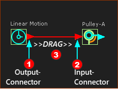
The design of each Function-Block (FB) icon is to help you identify its function. Also, you can enable Show Function-Block names to show their names in the graphics-area, above the Function-Block - see Edit menu > Application-Settings Graphics tab > Display Options. You can also rename Function-Block elements. For example, in this image, there are two Function-Blocks that also show their names: •a Linear-Motion FB - its name is Linear-Motion •a Motion-Dimension FB - has been renamed to Pulley-A The output-connector is to the right of a FB. The input-connector is to the left of a FB. A wire is between an output-connector and input-connector. Motion-values flow from FB to FB, along wires from an output-connector to an input-connector. |
To Connect FBs
Drag Wires from Output-Connector to Input-Connectors |
|
|
To connect a wire between two Function-Blocks: 1.Move your mouse-pointer above the output-connector 2.... mouse-button down ... 3.... drag a wire 4.... mouse-button-up. Now, there is a wire between the output-connector and the input-connector of two FBs. 5.Do 1 to 4 again and again to add more wires. Left < Video: How to connect wires between Function-Blocks. |
 Video: How to connect FBs |
|
About Motion-Values
As the Master Machine Angle (MMA) cycles (ALT+C to cycle the MMA continuously), motion-values flow instantly along wires between and through Function-Blocks. |
|
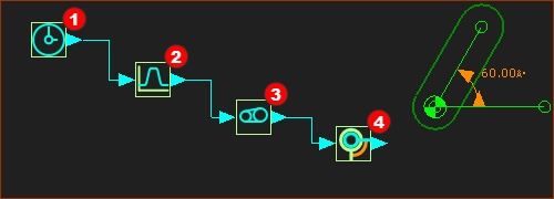
Example of the flow of motion-values along wires and through four FBs: There is an equation, or function, associated with each type of Function-Block. The equation has parameters that you can edit to modify the function.
The (default) motion-values at the output-connector of this Linear-Motion FB are equal to the Master Machine Angle ( 0 → 360) Therefore, when you cycle the machine (ALT+C) the output from the Linear-Motion FB changes at the same rate as the Master Machine Angle.
The Motion FB makes a link, similar to a hyperlink, with a motion name in MotionDesigner. The motion-values at the input-connector to the Motion FB relate to the X-axis values of the motion. The motion-values at its output-connector are the Y-axis values of the motion. Edit the Motion FB to link with a different motion in MotionDesigner.
The Gearing FB has three parameters. It can multiply motion-values at its input connector, and add or subtract a number from the input and/or output. If the input is 0 - 360, and the Gearing Ratio parameter is 2, and you add 40 to the output (after you multiply by 2), then its output will change from 40 to 760.
The Motion-Dimension FB uses the motion-values at its input-connector to control the motion of a Motion-Part. The Motion-Part in this case is a Rocker. It is possible to offset the initial position of the Rocker. You must edit the Base-Value parameter with the Motion-Dimension dialog. Thus, if the Base-Value is 20, the Rocker moves from 60º to 780º within the 0 – 360 cycle of the Master Machine Angle. |
The Kinematic Function-Blocks
“Motion Providers”: Provide motion-values. |
|
|
•Linear-Motion FB •One output-connector |
|
•Measurement FB - Point to Line (Linear); Line to Line(Angular); 3 Points (Angular) •One output-connector |
|
•Measurement FB - Point to Point (Linear) •Two output-connectors |
|
•Point-Data FB •Three output-connectors |
“Motion Processors”: Process motion-values with a function |
|
|
•Motion FB •One input-connector and one output-connector |
|
•Gearing FB •One input-connector and one output-connector |
“Motion-Dimension FB”: Control the angle or position of a Motion-Part relative to a different Part. |
|
|
•Motion-Dimension FB – Rocker •One input-connector and one output-connector |
|
•Motion-Dimension FB – Slider •One input-connector and one output-connector |
“Motion-Paths FB”: Control the position of a Motion-Point along a sketch-path. |
|
|
•Motion-Path FB •One input-connector |