The Kinematic Function-Blocks (FBs)
Function-Blocks provide motion, process motion, to control the position of Motion-Parts or Motion-Points.
The Function-Blocks calculate Linear or Angular Position, Velocity, and Acceleration. at all times.
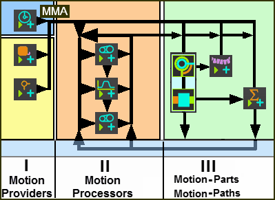
Schematics for Connecting Function-Blocks
 Schematic of how you can connect Function-Blocks |
||
Motion Providers |
Motion Processors |
Motion-Parts |
Motion Provider FBs include: Linear-Motion FB Default output is equal to the MMA. The Linear-Motion FB must be in the first kinematic-chain in a Mechanism-Editor. Point-Data FB and Measurement FB The output from a Measurement FB and Point-Data FB can be the independent variable and be the input to a Motion FB, a Motion-Dimension FB, or a Motion-Path FB. |
Motion Processor FBs include: Motion FB The value at its input is mapped to the X-axis of a Motion you select from MotionDesigner, and the output is the Y-axis motion-value. Gearing FB For each value at the input-connector, we use the parameters you edit and the linear equation, to calculate a new value at the output. |
Motion-Dimension FB •Rocker - rotate a Part •Slider - slide a Part Motion-Dimension FBs control the distance or angle between two Parts. |
Motion-Points |
||
Motion-Path FB: •Motion-Point(s) slide along a sketch-element |
||
Notes |
||
Motion-Providers 1.Do not have an input-connector. 2.Typically, the Linear-Motion FB is the independent input to other Function-Blocks. 3.We can also use the data from Point-Data FB or a Measurement FB at Motion-Providers: •as the X-axis (input) for a Motion FB •as the input to a Motion-Dimension FB - see Motion-Parts / Motion-Points - See Step 6.5 •simply report kinematic motion-values, with a Graph FB, for design and kinematic analysis |
Motion-Processors 1.It is possible to connect many Motion Processors in series. 2.It is not always necessary to use these Function-Blocks – the Motion-Parts can get their motion-values directly from the Motion Providers. 3.Design the Motion FB in MotionDesigner, usually the X-axis has a range from 0 to 360. However, the range of values at the input-connector do not need to be from 0 to 360. |
Motion-Parts and Motion-Points. 1.Use a Motion-Dimension FBs to control the angle or position of a Part. 2.Use a Motion-Path FB to control the position of a Motion-Point along a sketch-path. |