Background:
The chain moves with constant velocity. Now, we want the chain to index. An index motion has: 1.An Index-Period: The chain moves to a new position. 2.A Dwell-Period: The chain does not move. We must change the motion-values that we give to the kinematic-chains. We connect new Function-Blocks to the input-connector of the existing Motion-FBs that control the motions to Slider-X and Slider-Y. |
 Step 15.6: Video of Pattern

Indexing Belt
![]() Function-Blocks for a Constant Velocity Chain
Function-Blocks for a Constant Velocity Chain
|
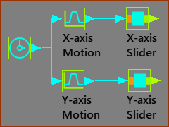
Function-Blocks for a Constant-Velocity chain These are the Function-Blocks to model the Constant Velocity chain. The MMA is the independent variable at the input of the X-axis & Y-axis Motion FBs. Each MMA value at the input to the Motion FBs has a corresponding value at its output. You define the output by the design of the motion in Motion-Designer. |
We now want the chain to index forward by one chain-link for an Index-Period then remain in a fixed position got a Dwell-Period. We want the motion to repeat 12 times in one machine cycle of the MMA. When the chain moves at Constant-Velocity, the input to the Motion FBs steadily increases from 0 to 360 for each machine-cycle. The output from the Motion FBs control Slider-X and Slider-Y to move the chain by one chain-length. To index the Indexing-Chain by one chain-link, the input to the Motion FBs (that control the Slider-X and Slider-Y) must increase by 30º, (say 0 to 30º) and remain at the new input value (say 30º) so that the chain dwells. To move the Indexing-Chain again by one more chain-link, we must increase the input to the Motion FBs by another 30º, (say 30 to 60º) or a total of 60º. and remain at the new input value (say 60º) so that the chain dwells again. To index the Indexing-Chain 12 times, the input to the Motion FBs must increase by 30º, 12 time, to eventually increase to 360º. There are two motions that you can design: OPTION 1: 12 × Index and 12 × Dwell segments - a total of 24 segments The output increases to 360º, in 30º index steps, as the input increases to 360º. Option 2: 1 × Index and 1 × Dwell segment - a total of 2 segments The output increases by 30º as the input increases to 360º. We must be able to repeat this simple motion 12 times. To do this, we increase the input to the Motion FB to 12×360 = 4320º over one machine-cycle. Also, we must use the Motion FB option Accumulate so that the output accumulates to 360 with 12 x 30º indexes. |
| OPTION 1 |
12 × index and dwell periods in one machine cycle. Advantage: Less complexity of the Function-Blocks. Disadvantage: If you want to edit the Motion-Law, or the Index-Period, you must edit a complex motion. Overall, I do not think Option 1 is the best solution. |
||
 12x Index and Dwell |
This is an example motion that has 12 identical index-periods and 12 dwell-periods in one machine-cycle. The Motion-Width (X-axis) is 360, and the Motion displacement (Y-axis) is 360. If you want to change the motion-law or the index-period, you must edit all 24 segments, and not make a mistake! |
|
 FBs for 12x Index motion |
These are the Function-Blocks. There is 1 x Motion FB. It has a link to the Motion with 12 x indexes - see above. The motion controls the Slider-X and Slider-Y directly. We add 30º to the motion output so that the input to Slider-X2 and Slider-Y2 is advanced by 30º. The pulleys rotate by 72º each index rather than 30º. Thus the input to the Pulley's is multiplied by 2.4. |
|
| OPTION 2 |
1 × Index and Dwell Advantage: If you want to edit the Motion-Law, the Index-Period or the Dwell-Period, you only need to edit two segments. Disadvantage: You must add one more Function-Block. |
||
 1 x Index and Dwell |
This example Index motion has 2 segments. •Segment 1: Indexing •Segment 2: Dwell The Motion-Width is 360º, and the Motion displacement is 30º. If you want to change the motion-law or the index-period, you only need to edit 2 segment. |
|
 FBs for 12x Index motion |
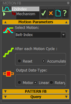
These are the Function-Blocks. The Motion FB with the name 1×Index has the link to Index Motion - see above. The output of 1×Index increases from 0 to 30º as the input increases from 0 to 360º. If we increase the input from 0 to 4320º (12×360º), the output from 1xIndex (0 to 30º) will repeat 12x. We can accumulate the output, so that it indexes 0-30, 30-60, 60-90, ... 330-360º. To provide an input to 1×Index of 0 to 4320º, we use a Gearing FB and enter 12 as the Gearing Ratio. |
|
|
Motion FB (1xIndex) You must use Accumulate Output radio-button in the Motion FB dialog. 1.Open the Motion FB dialog 2.Select After each Motion-Cycle : Accumulate. |
|