Objective:
To convert the DXF-Drawing to MechDesigner sketch-elements, and then to add an Extrusion.
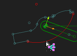
1.Select DXF-Entities that are in the DXF-Outline
2.Copy and convert the DXF-Entities to MechDesigner sketch-elements, as a sketch-loop.
3.Add a Profile / Extrusion to the sketch-loop
Convert DXF-Entities into MechDesigner Lines and Arc separator
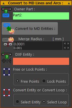 |
STEP 1: Select a Owner-Part The Owner-Part is usually the Part to which the CAD-Line is a child. However, you can also covert the DXF-Entities on a different Part.
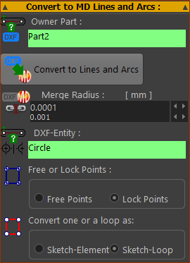
STEP 2: Select a DXF-Entity The DXF-Entity box refers to DXF Lines or DXF Circles/Arcs in the DXF-Drawing
The name of the DXF-Entity should be in the DXF Entity box. The button becomes colorized. Before you click the button, choose one from each of the following: STEP 3: Enable Free Points or Lock Points
STEP 4: Select Sketch-Element or Sketch-Loop
|
||||
 |
|||||
 |
|||||
 DXF-Entities AND Sketch-Loop with Locked-Points |
STEP 5: Convert the DXF-Entities to a sketch-loop (if possible)
Now, the new sketch-elements AND the DXF-Entities are in the graphics-area. The color of the DXF-Entities are different to the sketch-elements
|
||||
 Sketch-elmenets as Sketch-Loop with Locked-Points |
It is sometimes convenient to remove the DXF-Entities from the graphics-area and CAD-Line after you click the the button. STEP 6: Delete the DXF-Entities from the CAD-Line and Part.
The new sketch-elements stay in the Part - see left. If the Sketch-Loop option is successful. STEP 7: Click |
Use the Add Profile command
If the button finds a sketch-loop, add a Profile / Extrusion to the sketch-loop in the usual way. If the button did not find a sketch-loop, edit the Part to add sketch-elements to make a sketch-loop. |
||||
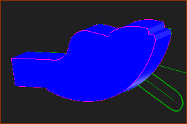 |
STEP 1: Add a Profile to the sketch-loop
There is a new Profile / Extrusion in the graphics-area. STEP 2: Show the Extrusion
|
|||