Objective:
1.Add a DXF-Element, linked to a DXF-Drawing, to the Assembly-Tree.
2.Show the DXF-Drawing and show it in the graphics-area.
3.Align it with the CAD-Line.
Top-Tips
Before, in your other CAD, you save a DXF-Drawing : •Remove hidden lines •Explode all Blocks (we cannot import a DXF with Blocks) •Save the DXF-Drawing as AutoCAD Release 12 or as early as is available Note We will not import TEXT or Splines. |
Open a DXF-Drawing file-type
 |
STEP 1: Open DXF-Drawing file-type
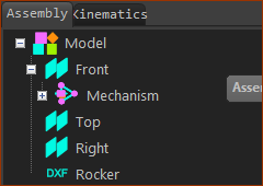
A DXF-element is now in the Assembly-Tree. It is helpful to rename elements. STEP 2: Rename the DXF-Element to the DXF-Drawing file-name |
Open a CAD-Line dialog
 Double-click a CAD-Line  CAD-Line dialog-box > DXF tab |
STEP 1: If necessary, add Part, or a CAD-Line to the Base-Part
There is now a CAD-Line in the graphics-area. STEP 2: Edit the CAD-Line. To open the CAD-Line dialog:
The CAD-Line dialog opens. STEP 3: Click the DXF tab |
Link the DXF-Element and DXF-Drawing with the CAD-Line
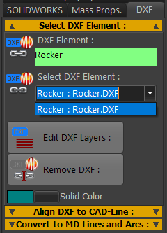 |
STEP 1: Link the DXF-Element with the CAD-Line:
The DXF-Drawing is now in the graphics-area.
If the DXF-Drawing is at the correct location, and orientation, you can close CAD-Line dialog now.
Or you can continue with other options. |
|
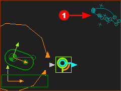 |
The DXF-Drawing is in the graphics-area, in the DXF-Outline format. You may need to Zoom-Out to find the DXF-Drawing. If we want to re-align the DXF-Drawing with the CAD-Line |
|
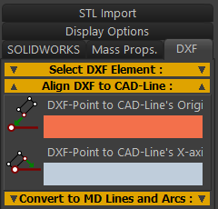 |
STEP 2: Align the DXF-Drawing with the CAD-Line: DXF-Point to CAD-Line's Origin (its start-Point)
|
|
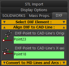 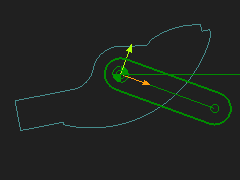 |
DXF-Point to CAD-Line's X-axis
The DXF-Drawing moves to align with the CAD-Line. If you make a mistake, click the boxes again. When you close the CAD-Line dialog, the DXF Points do not display.
|