CV Inverse Crank

<< Click to Display Table of Contents >>

Navigation:  MotionDesigner Reference & User Interface > Motion Laws / Cam-Laws for Segments >

CV Inverse Crank

CV (Constant-Velocity) Inverse Crank

Motion-Description

We can explain this motion-law if we project the motion of a Point that is at the end of a rotating Crank onto a Line.

When a Crank rotates with Constant angular velocity, the motion of a Point that we project onto any Line is Simple-Harmonic-Motion.

When the Crank rotates with the CV-Inverse-Crank motion-law, the motion of a Point that we project onto a particular Line is Constant Linear Velocity.

Motion-Values

Start Position - control with the Segment-Parameters - see below.

End Position - control with the Segment-Parameters - see below.

You CANNOT control the:

Start Velocity and End Velocity

Start Acceleration and End Acceleration

Start Jerk and End Jerk

The actual velocity, acceleration, and jerk values, and the distance the Point moves along the Line are a function of the:

Segment-Width

Length of the Rocker/Crank

Segment-Parameters

Segment Parameters

Typical Segment-Parameters for the CV Inverse-Crank motion-law

Typical Segment-Parameters for the CV Inverse-Crank motion-law

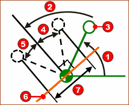
Schematic of Crank made to give a constant linear velocity from Angle(4) (defined by Start-Position(1), to Angle(5), defined by the End-Position(2).

Svchematic to help you understand how to use the CV Inverse Crank motion-law.

The Segment-Parameters are ANGLES:

Min VelRed-14-2 (Minimum Velocity)

The Angle relative to the Base-ValueRed-14-1b angle that you control with the Motion-Dimension FB at which the Crank rotates with Minimum-Velocity.

Rel StartRed-14-4 (Relative Start)

The angle, relative to the angle you control with Min VelRed-14-2, at which PointRed-14-3 starts to move along the Orange Line with Constant-Velocity.

Rel EndRed-14-5 (Relative End)

The angle, relative to the angle you control by Min Vel Red-14-2, at which PointRed-14-3 ends the move along the Orange Line with Constant-Velocity.

Note:

The Crank rotates Counter-Clockwise when Rel. Start is Negative and Rel. End is a Positive.

The Crank rotates Clockwise when Rel. Start is Positive and Rel. End is Negative.

Segment-Range

Start-Range

End- Range

0 ≤ Start-Range < End-Range ≤ 1


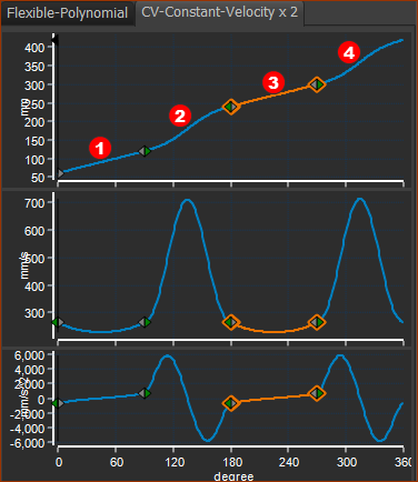
Example motion with 2 x CV Inverse-Crank motion-laws

Example motion with 2 x CV Inverse-Crank motion-laws

EXAMPLE

Two CV Inverse Crank segments in one Motion.

Segment Red-14-1b: Constant-Velocity Inverse-Crank

X-axis : 0 to 90º

Segment Parameters are:

Angle of Minimum Velocity = 90º

Relative Start Angle = –30º

Relative End = 30º

With these Parameters:

X-axis = 0º ; Y–axis = 60º.

X-axis =90 ; Y–axis = 120º

Segment Red-14-2: Flexible-Polynomial

X-axis : 90 to 180º

Y-axis at Start P=120. V, A, J flow from the end of the Constant-Crank-Velocity Segment.

Y-axis at End 240º

Segment Red-14-3: Constant-Velocity Inverse-Crank

X-axis : 180 to 270º

Segment Parameters are:

Angle of Minimum Velocity = 270º

Relative Start Angle = –30º

Relative End = 30º

With these Parameters:

X-axis = 180º ; Y–axis = 240º

X-axis = 270 ; Y–axis = 300º

Segment Red-14-4: Flexible-Polynomial

X-axis : 90 to 180º

Y-axis P at Start = 300º. V, A, J flow from the end of the Constant-Crank-Velocity Segment.

Y=axis at End = 420º.